How to Use Motor Controller: Examples, Pinouts, and Specs
Introduction
The FEETECH 2CH Motor Controller is a versatile electronic device designed to regulate the speed, direction, and torque of electric motors by controlling the power supplied to them. This motor controller supports two channels, allowing it to independently control two DC motors. It is ideal for robotics, automation systems, and other applications requiring precise motor control.
Explore Projects Built with Motor Controller

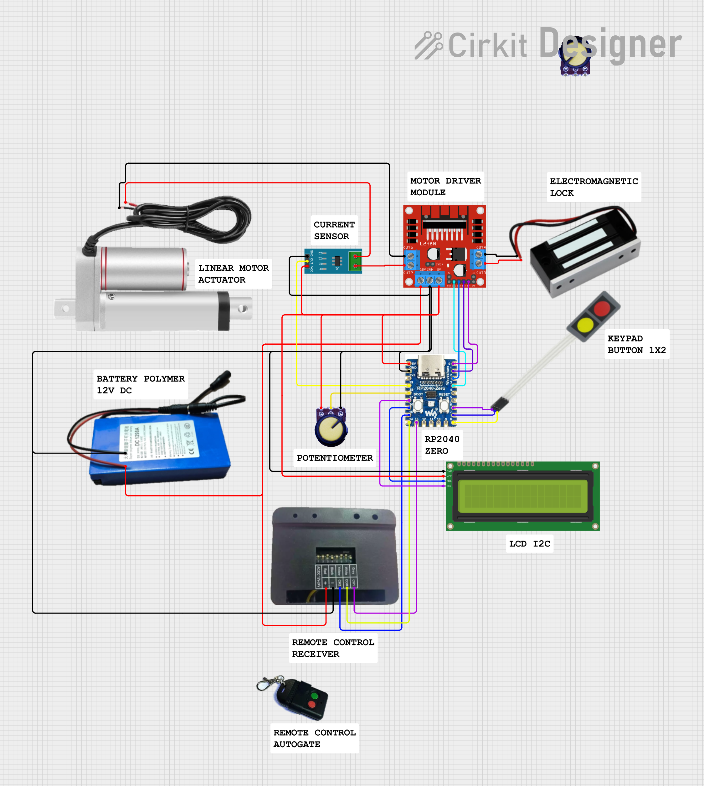
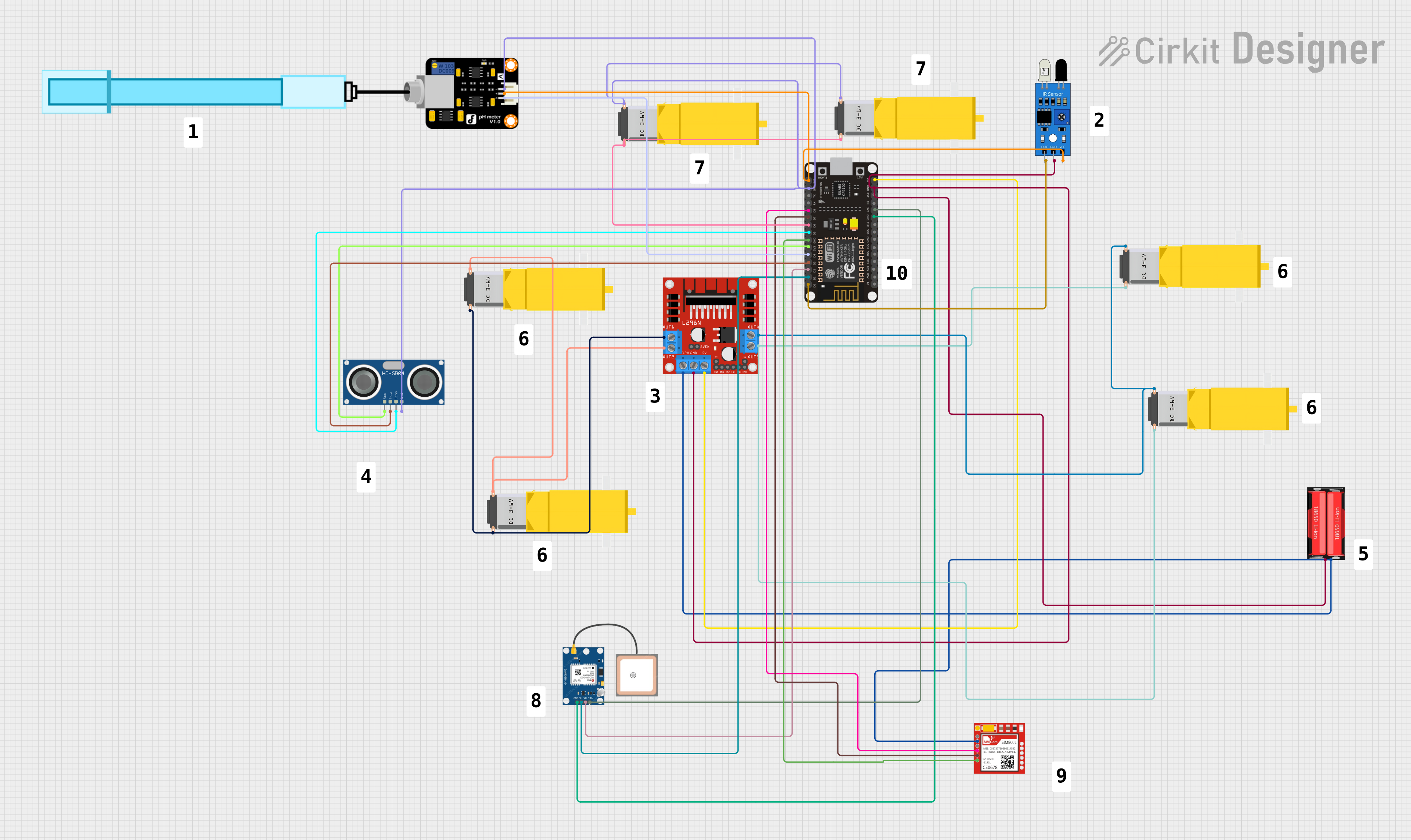
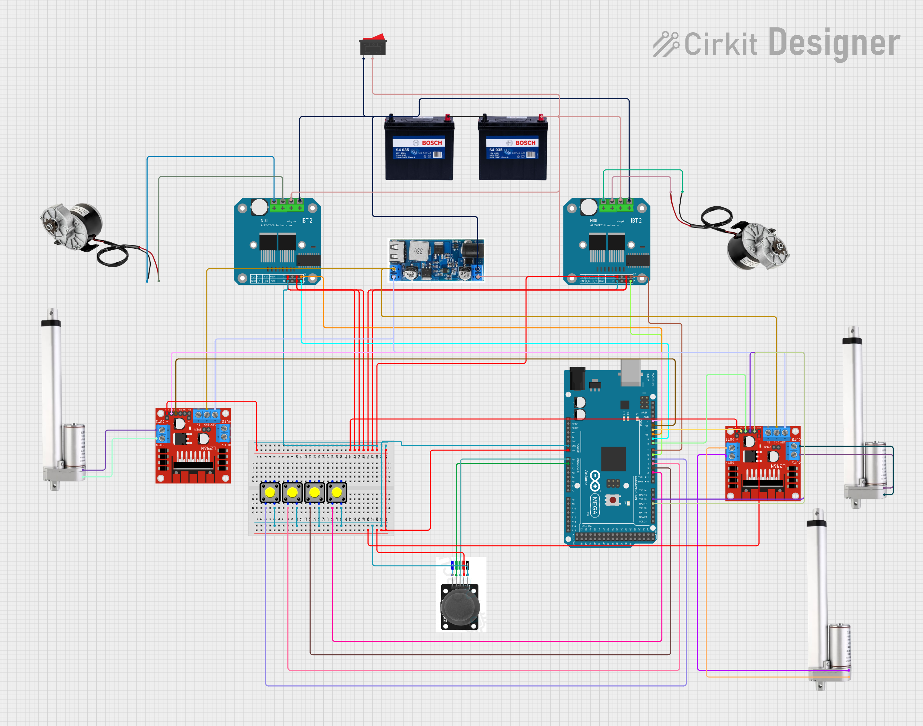
Explore Projects Built with Motor Controller
Common Applications and Use Cases
- Robotics: Controlling the movement of robot wheels or arms.
- Automation: Driving conveyor belts or automated systems.
- Remote-controlled vehicles: Managing speed and direction.
- DIY projects: Building motorized systems for hobbyist applications.
Technical Specifications
The following table outlines the key technical details of the FEETECH 2CH Motor Controller:
| Specification | Value |
|---|---|
| Manufacturer | FEETECH |
| Part ID | 2CH-motor-controller |
| Number of Channels | 2 |
| Input Voltage Range | 6V to 24V |
| Maximum Output Current | 10A per channel |
| Control Interface | PWM (Pulse Width Modulation) |
| Logic Voltage | 3.3V or 5V compatible |
| Operating Temperature | -20°C to 85°C |
| Dimensions | 60mm x 40mm x 15mm |
| Weight | 30g |
Pin Configuration and Descriptions
The motor controller has the following pin layout:
| Pin Name | Type | Description |
|---|---|---|
| VIN | Power Input | Connect to the positive terminal of the power supply (6V to 24V). |
| GND | Power Ground | Connect to the ground terminal of the power supply. |
| M1+ | Motor Output | Positive terminal for Motor 1. |
| M1- | Motor Output | Negative terminal for Motor 1. |
| M2+ | Motor Output | Positive terminal for Motor 2. |
| M2- | Motor Output | Negative terminal for Motor 2. |
| PWM1 | Control Input | PWM signal input for Motor 1 speed control. |
| DIR1 | Control Input | Direction control input for Motor 1 (HIGH for forward, LOW for reverse). |
| PWM2 | Control Input | PWM signal input for Motor 2 speed control. |
| DIR2 | Control Input | Direction control input for Motor 2 (HIGH for forward, LOW for reverse). |
| EN | Control Input | Enable pin for the motor controller (HIGH to enable, LOW to disable). |
Usage Instructions
How to Use the Component in a Circuit
- Power Supply: Connect the VIN and GND pins to a power source within the specified voltage range (6V to 24V).
- Motor Connections: Attach the motors to the M1+/M1- and M2+/M2- terminals.
- Control Signals: Use a microcontroller (e.g., Arduino UNO) to send PWM signals to the PWM1 and PWM2 pins for speed control. Use the DIR1 and DIR2 pins to set the direction of each motor.
- Enable the Controller: Set the EN pin HIGH to activate the motor controller.
Important Considerations and Best Practices
- Ensure the power supply voltage matches the motor's operating voltage to avoid damage.
- Use appropriate heat dissipation methods if operating at high currents for extended periods.
- Add a flyback diode across the motor terminals to protect the controller from voltage spikes.
- Verify that the PWM signal frequency is compatible with the motor controller (typically 1kHz to 20kHz).
Example Code for Arduino UNO
Below is an example Arduino sketch to control two motors using the FEETECH 2CH Motor Controller:
// Define motor control pins
const int EN_PIN = 8;      // Enable pin
const int PWM1_PIN = 9;    // PWM pin for Motor 1
const int DIR1_PIN = 7;    // Direction pin for Motor 1
const int PWM2_PIN = 10;   // PWM pin for Motor 2
const int DIR2_PIN = 6;    // Direction pin for Motor 2

void setup() {
  // Set pin modes
  pinMode(EN_PIN, OUTPUT);
  pinMode(PWM1_PIN, OUTPUT);
  pinMode(DIR1_PIN, OUTPUT);
  pinMode(PWM2_PIN, OUTPUT);
  pinMode(DIR2_PIN, OUTPUT);

  // Enable the motor controller
  digitalWrite(EN_PIN, HIGH);
}

void loop() {
  // Motor 1: Forward at 50% speed
  digitalWrite(DIR1_PIN, HIGH);  // Set direction to forward
  analogWrite(PWM1_PIN, 128);    // Set speed (128 = 50% duty cycle)

  // Motor 2: Reverse at 75% speed
  digitalWrite(DIR2_PIN, LOW);   // Set direction to reverse
  analogWrite(PWM2_PIN, 192);    // Set speed (192 = 75% duty cycle)

  delay(2000);  // Run motors for 2 seconds

  // Stop both motors
  analogWrite(PWM1_PIN, 0);      // Stop Motor 1
  analogWrite(PWM2_PIN, 0);      // Stop Motor 2

  delay(2000);  // Wait for 2 seconds before repeating
}
Troubleshooting and FAQs
Common Issues and Solutions
Motors Not Running:
- Ensure the EN pin is set HIGH to enable the motor controller.
- Verify that the power supply voltage is within the specified range.
- Check the motor connections and ensure they are secure.
Motor Running in the Wrong Direction:
- Reverse the logic level on the DIR1 or DIR2 pin.
- Swap the motor's M+ and M- connections.
Overheating:
- Ensure the current draw of the motors does not exceed 10A per channel.
- Use a heatsink or cooling fan if operating at high currents.
PWM Signal Not Working:
- Verify that the PWM signal frequency is within the supported range (1kHz to 20kHz).
- Check the microcontroller's PWM pin configuration.
FAQs
Q: Can I use this motor controller with a 3.3V logic microcontroller?
A: Yes, the controller is compatible with both 3.3V and 5V logic levels.
Q: What type of motors can I use with this controller?
A: The controller is designed for brushed DC motors with a voltage range of 6V to 24V.
Q: How do I control the speed of the motors?
A: Use a PWM signal on the PWM1 and PWM2 pins to adjust the motor speed. The duty cycle of the PWM signal determines the speed.
Q: Can I control only one motor with this controller?
A: Yes, you can use only one channel if needed. Leave the unused channel's pins unconnected.
By following this documentation, you can effectively integrate the FEETECH 2CH Motor Controller into your projects for precise motor control.