How to Use 8x8 Led Matrix: Examples, Pinouts, and Specs
Introduction
The 8x8 LED Matrix (Manufacturer: Edusoft, Part ID: Led Matrix) is a versatile display component consisting of 64 individual LEDs arranged in an 8x8 grid. Each LED can be individually controlled to display characters, symbols, or patterns, making it ideal for a wide range of applications. This component is commonly used in projects such as digital clocks, scrolling text displays, gaming devices, and educational tools.
Explore Projects Built with 8x8 Led Matrix


Explore Projects Built with 8x8 Led Matrix
Common Applications
- Digital signage and scrolling text displays
- Visual indicators in embedded systems
- Educational projects for learning about multiplexing
- Gaming devices (e.g., retro-style displays)
- Custom animations and patterns in DIY electronics
Technical Specifications
The following table outlines the key technical details of the 8x8 LED Matrix:
| Parameter | Specification |
|---|---|
| Manufacturer | Edusoft |
| Part ID | Led Matrix |
| LED Configuration | 8 rows × 8 columns (64 LEDs) |
| Operating Voltage | 3.3V to 5V |
| Forward Voltage (per LED) | 2.0V to 2.2V (typical) |
| Maximum Current (per LED) | 20mA |
| Dimensions | 32mm × 32mm × 8mm |
| LED Color | Red (or other variants depending on model) |
| Interface Type | Multiplexed (row/column control) |
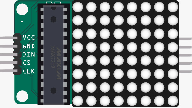
Pin Configuration
The 8x8 LED Matrix uses a multiplexed row and column control system. Below is the pin configuration for the component:
| Pin Number | Description | Functionality |
|---|---|---|
| 1-8 | Row Pins (R1-R8) | Controls the rows of the matrix |
| 9-16 | Column Pins (C1-C8) | Controls the columns of the matrix |
Note: The exact pin numbering may vary depending on the specific model. Refer to the datasheet for precise details.
Usage Instructions
How to Use the 8x8 LED Matrix in a Circuit
- Power Supply: Connect the matrix to a 3.3V or 5V power source, ensuring the current does not exceed the maximum rating.
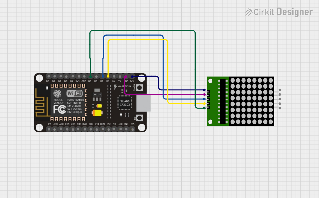
- Control Method: Use a microcontroller (e.g., Arduino UNO) to control the rows and columns. Multiplexing is required to light up individual LEDs.
- Resistors: Use current-limiting resistors (typically 220Ω to 330Ω) to prevent damage to the LEDs.
- Driver ICs: For ease of control, consider using a driver IC like the MAX7219 or 74HC595 shift register.
Example Circuit with Arduino UNO
Below is an example of connecting the 8x8 LED Matrix to an Arduino UNO using a MAX7219 driver IC:
Wiring Diagram
- Connect the DIN pin of the MAX7219 to Arduino pin 11.
- Connect the CS pin of the MAX7219 to Arduino pin 10.
- Connect the CLK pin of the MAX7219 to Arduino pin 13.
- Connect the 8x8 LED Matrix to the MAX7219 as per the datasheet.
Example Code
// Include the LedControl library for MAX7219 control
#include <LedControl.h>

// Initialize the LedControl object
// Parameters: DIN pin, CLK pin, CS pin, number of devices
LedControl lc = LedControl(11, 13, 10, 1);

void setup() {
  // Wake up the MAX7219 from power-saving mode
  lc.shutdown(0, false);
  // Set brightness (0 = dim, 15 = bright)
  lc.setIntensity(0, 8);
  // Clear the display
  lc.clearDisplay(0);
}

void loop() {
  // Display a simple pattern (diagonal line)
  for (int i = 0; i < 8; i++) {
    lc.setLed(0, i, i, true); // Turn on LED at row i, column i
    delay(200);              // Wait for 200ms
  }
  delay(1000);               // Pause for 1 second
  lc.clearDisplay(0);        // Clear the display
}
Important Considerations
- Multiplexing: Only one row or column is active at a time. Use rapid switching to create the illusion of a fully lit display.
- Current Limiting: Always use resistors or a driver IC to limit current through the LEDs.
- Power Supply: Ensure the power supply can handle the total current draw of the matrix.
Troubleshooting and FAQs
Common Issues
LEDs Not Lighting Up:
- Check the wiring and ensure all connections are secure.
- Verify that the power supply voltage matches the matrix's requirements.
- Ensure current-limiting resistors or driver ICs are properly connected.
Dim or Flickering LEDs:
- Check for insufficient power supply current.
- Verify the multiplexing code for proper timing and delays.
Incorrect Patterns Displayed:
- Double-check the row and column connections.
- Ensure the software logic matches the matrix's pin configuration.
FAQs
Q: Can I control the 8x8 LED Matrix without a driver IC?
A: Yes, but it requires more GPIO pins and complex multiplexing code. Using a driver IC like the MAX7219 simplifies the process significantly.
Q: What is the maximum brightness I can achieve?
A: Brightness depends on the current supplied to each LED. Ensure the current does not exceed 20mA per LED to avoid damage.
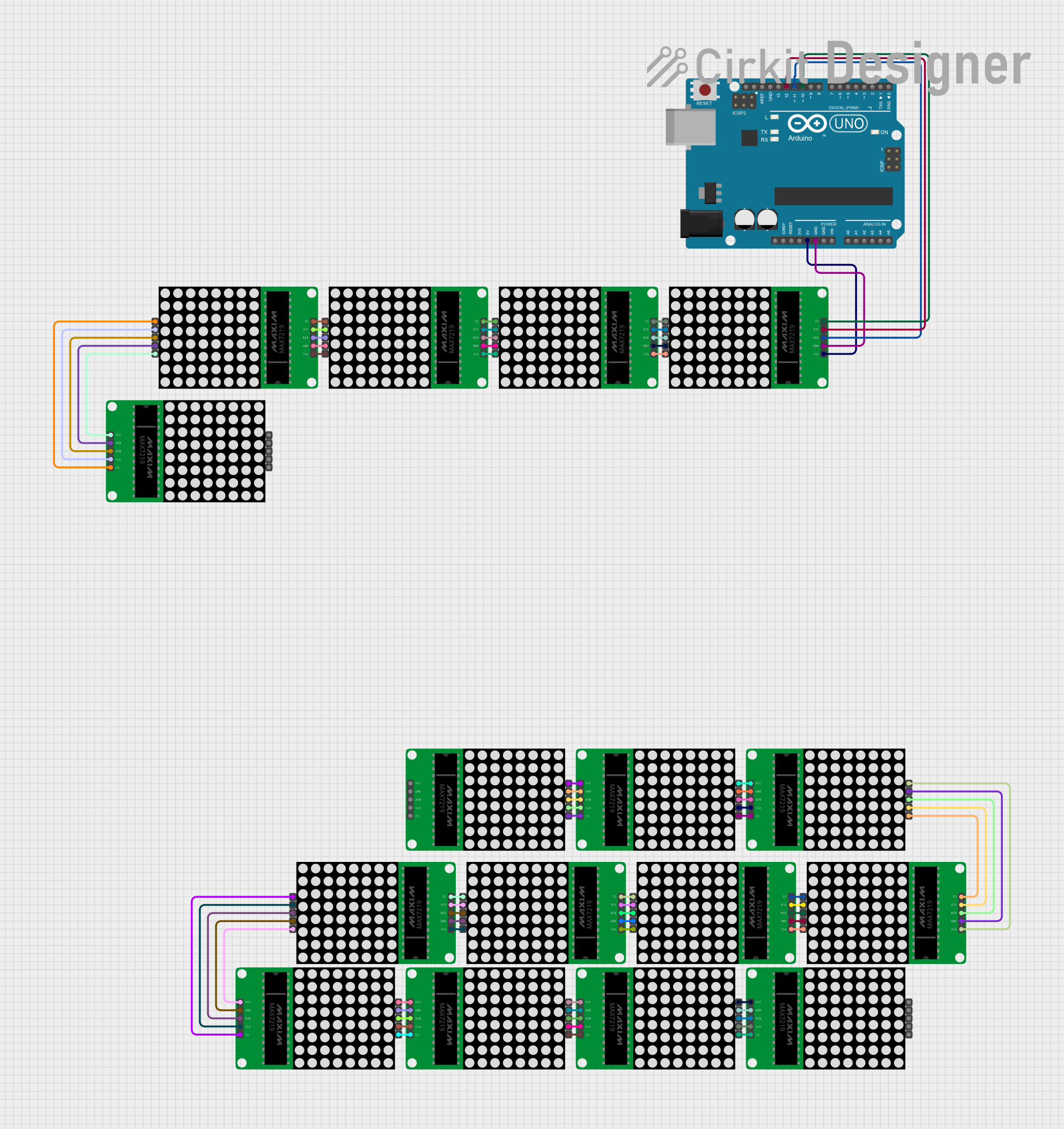
Q: Can I daisy-chain multiple matrices?
A: Yes, if using a driver IC like the MAX7219, you can daisy-chain multiple matrices and control them with a single microcontroller.
By following this documentation, you can effectively integrate the Edusoft 8x8 LED Matrix into your projects and create stunning visual displays!