How to Use OXY-LC Interface Board: Examples, Pinouts, and Specs
Introduction
The OXY-LC Interface Board (OXY-LC-485), manufactured by SST Sensing, is a specialized circuit board designed to interface with OXY-LC oxygen sensors. It facilitates seamless communication and data transfer between the sensor and external devices such as microcontrollers, PLCs, or industrial systems. The board supports RS-485 communication, making it suitable for robust and long-distance data transmission in industrial and environmental monitoring applications.
Explore Projects Built with OXY-LC Interface Board
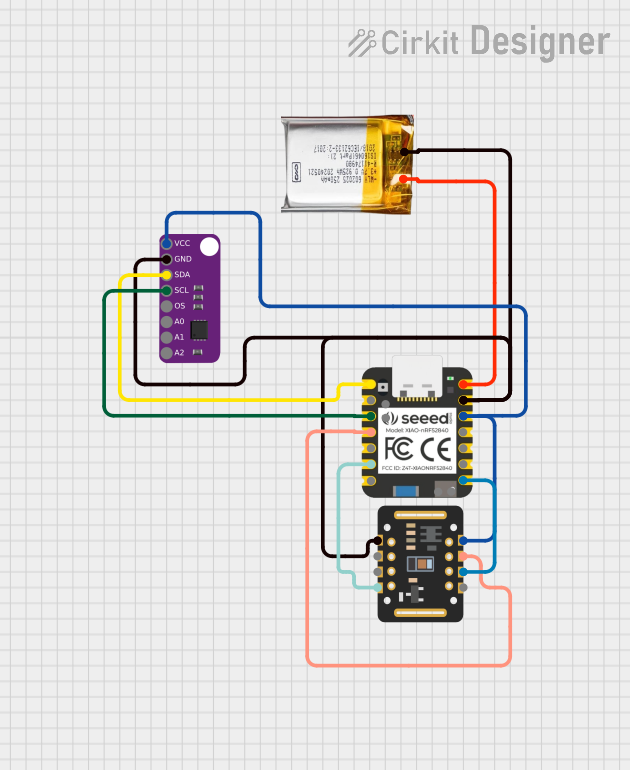
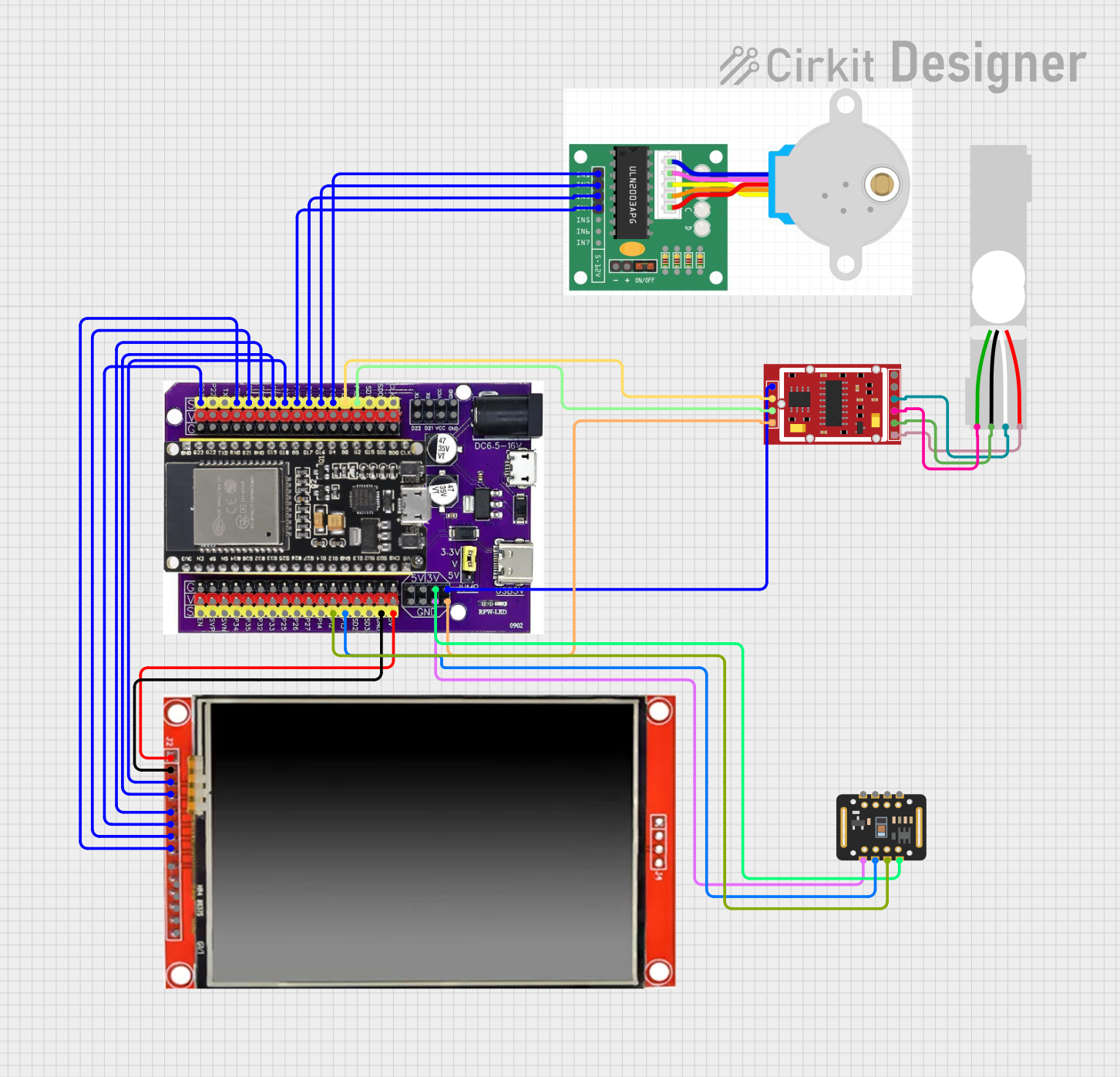

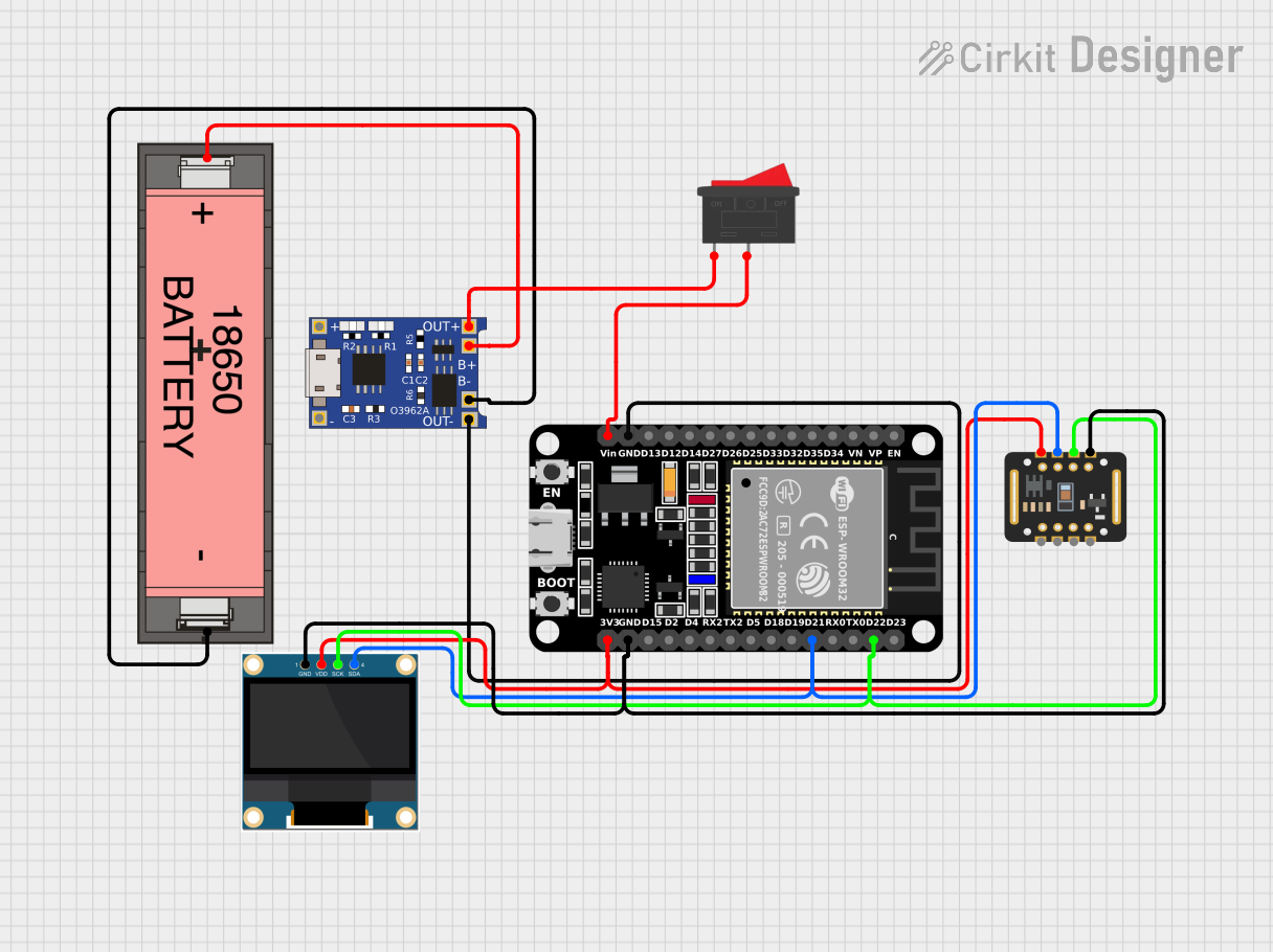
Explore Projects Built with OXY-LC Interface Board
Common Applications and Use Cases
- Industrial Process Control: Monitoring oxygen levels in manufacturing processes.
- Environmental Monitoring: Measuring oxygen concentration in air or water.
- Medical Equipment: Integration into devices requiring precise oxygen sensing.
- Research and Development: Prototyping and testing oxygen sensor-based systems.
Technical Specifications
Key Technical Details
| Parameter | Specification |
|---|---|
| Input Voltage | 5V DC ± 5% |
| Communication Protocol | RS-485 |
| Operating Temperature | -20°C to +60°C |
| Power Consumption | < 1W |
| Dimensions | 50mm x 25mm x 10mm |
| Connector Type | 4-pin Molex for sensor connection |
| Baud Rate | Configurable (default: 9600 bps) |
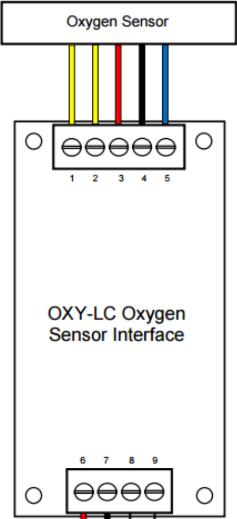
Pin Configuration and Descriptions
Sensor Connector (4-pin Molex)
| Pin Number | Name | Description |
|---|---|---|
| 1 | VCC | Power supply input (5V DC) |
| 2 | GND | Ground |
| 3 | TX+/A | RS-485 differential signal (positive) |
| 4 | TX-/B | RS-485 differential signal (negative) |
RS-485 Communication Interface
| Pin Number | Name | Description |
|---|---|---|
| 1 | A (TX+) | RS-485 differential signal (positive) |
| 2 | B (TX-) | RS-485 differential signal (negative) |
| 3 | GND | Ground |
Usage Instructions
How to Use the Component in a Circuit
- Power Supply: Connect a regulated 5V DC power supply to the VCC and GND pins of the interface board.
- Sensor Connection: Attach the OXY-LC sensor to the 4-pin Molex connector on the board.
- RS-485 Communication: Connect the A (TX+) and B (TX-) pins to the RS-485 bus of your microcontroller or PLC.
- Baud Rate Configuration: Ensure the baud rate of your microcontroller matches the default or configured baud rate of the interface board (default: 9600 bps).
- Data Reading: Use the RS-485 protocol to send commands and receive oxygen concentration data from the sensor.
Important Considerations and Best Practices
- Power Supply: Use a stable and noise-free 5V DC power source to avoid communication errors.
- Termination Resistor: For long RS-485 bus lines, add a 120-ohm termination resistor between A and B lines at both ends of the bus.
- Grounding: Ensure a common ground between the interface board and the connected device.
- Cable Length: RS-485 supports long cable runs, but keep the length within 1200 meters for reliable communication.
- Sensor Warm-Up: Allow the sensor to stabilize for a few seconds after powering up before taking measurements.
Example Code for Arduino UNO
Below is an example of how to interface the OXY-LC Interface Board with an Arduino UNO using an RS-485 module.
#include <SoftwareSerial.h>

// Define RS-485 communication pins
#define RX_PIN 10  // Arduino pin connected to RS-485 RX
#define TX_PIN 11  // Arduino pin connected to RS-485 TX

// Create a SoftwareSerial object for RS-485 communication
SoftwareSerial rs485Serial(RX_PIN, TX_PIN);

void setup() {
  // Initialize serial communication for debugging
  Serial.begin(9600);
  // Initialize RS-485 communication
  rs485Serial.begin(9600);

  Serial.println("OXY-LC Interface Board Communication Started");
}

void loop() {
  // Send a command to the OXY-LC sensor (example command: 0x01 0x03 0x00 0x00 0x00 0x01 0x85 0xDB)
  byte command[] = {0x01, 0x03, 0x00, 0x00, 0x00, 0x01, 0x85, 0xDB};
  rs485Serial.write(command, sizeof(command));

  // Wait for a response
  delay(100);

  // Check if data is available
  if (rs485Serial.available()) {
    Serial.print("Sensor Response: ");
    while (rs485Serial.available()) {
      byte response = rs485Serial.read();
      Serial.print(response, HEX);
      Serial.print(" ");
    }
    Serial.println();
  }

  // Wait before sending the next command
  delay(1000);
}
Notes:
- Replace the example command with the appropriate command for your specific application.
- Ensure the RS-485 module is properly connected to the Arduino UNO.
Troubleshooting and FAQs
Common Issues and Solutions
No Communication with the Sensor
- Cause: Incorrect baud rate or wiring.
- Solution: Verify the baud rate and ensure proper connections between the interface board, RS-485 module, and microcontroller.
Unstable Readings
- Cause: Noisy power supply or improper grounding.
- Solution: Use a regulated power supply and ensure a common ground between devices.
Data Corruption on Long Cables
- Cause: Missing termination resistors.
- Solution: Add 120-ohm termination resistors at both ends of the RS-485 bus.
Sensor Not Responding
- Cause: Sensor not properly connected or damaged.
- Solution: Check the sensor connection and replace the sensor if necessary.
FAQs
Q: Can I use a 3.3V microcontroller with the OXY-LC Interface Board?
A: Yes, but you will need a level shifter to convert the 3.3V logic to 5V for RS-485 communication.Q: What is the maximum cable length supported by RS-485?
A: RS-485 supports cable lengths up to 1200 meters, but ensure proper termination and shielding for long runs.Q: How do I change the baud rate of the interface board?
A: Refer to the OXY-LC Interface Board user manual for instructions on configuring the baud rate.Q: Can I connect multiple sensors to the same RS-485 bus?
A: Yes, RS-485 supports multi-drop communication. Assign unique addresses to each sensor.
This documentation provides a comprehensive guide to using the OXY-LC Interface Board effectively. For further assistance, consult the manufacturer's datasheet or technical support.