
How to Use ESP32 Shield Bornes 38PIN: Examples, Pinouts, and Specs
 Design with ESP32 Shield Bornes 38PIN in Cirkit Designer
Introduction
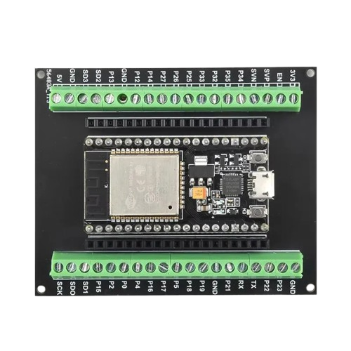
The ESP32 Shield Bornes 38PIN is a versatile shield designed to enhance the functionality of the ESP32 microcontroller. Manufactured by Generic with the part ID UNDO, this shield provides easy access to the ESP32's GPIO pins through a 38-pin layout. It also includes additional features such as power management and connectivity options, making it an ideal choice for prototyping and IoT applications.
Explore Projects Built with ESP32 Shield Bornes 38PIN
 Open Project in Cirkit Designer
 Open Project in Cirkit Designer
 Open Project in Cirkit Designer
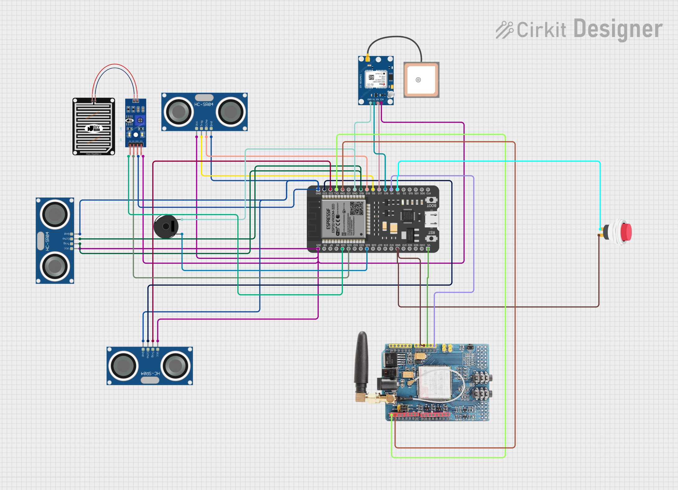 Open Project in Cirkit Designer
Explore Projects Built with ESP32 Shield Bornes 38PIN
Open Project in Cirkit DesignerOpen Project in Cirkit DesignerOpen Project in Cirkit DesignerOpen Project in Cirkit DesignerCommon Applications and Use Cases
- IoT (Internet of Things) devices and smart home projects
- Prototyping and development of embedded systems
- Wireless communication projects using Wi-Fi and Bluetooth
- Sensor integration and data acquisition
- Robotics and automation systems
Technical Specifications
The following table outlines the key technical specifications of the ESP32 Shield Bornes 38PIN:
| Specification | Details |
|---|---|
| Manufacturer | Generic |
| Part ID | UNDO |
| Microcontroller Support | ESP32 |
| Pin Count | 38 |
| Input Voltage Range | 5V (via USB) or 7-12V (via external power supply) |
| Output Voltage | 3.3V (regulated for ESP32) |
| Communication Protocols | UART, SPI, I2C, PWM, ADC, DAC |
| Connectivity | Wi-Fi, Bluetooth |
| Dimensions | 60mm x 30mm x 15mm |
| Operating Temperature | -40°C to 85°C |
Pin Configuration and Descriptions
The ESP32 Shield Bornes 38PIN provides access to the ESP32's GPIO pins through a 38-pin layout. Below is the pin configuration:
| Pin Number | Pin Name | Description |
|---|---|---|
| 1 | GND | Ground |
| 2 | 3V3 | 3.3V output (regulated) |
| 3 | VIN | Input voltage (7-12V) |
| 4 | EN | Enable pin (active high) |
| 5 | IO0 | GPIO0, used for boot mode selection |
| 6-19 | IO1-IO14 | General-purpose input/output pins |
| 20 | ADC1 | Analog-to-digital converter input |
| 21 | DAC1 | Digital-to-analog converter output |
| 22-37 | IO15-IO30 | General-purpose input/output pins |
| 38 | RST | Reset pin |
Usage Instructions
How to Use the Component in a Circuit
Powering the Shield:
- Connect the shield to a 5V USB power source or supply 7-12V via the VIN pin.
- The onboard voltage regulator will provide a stable 3.3V output for the ESP32.
Connecting the ESP32:
- Insert the ESP32 microcontroller into the shield's socket, ensuring proper alignment of pins.
Accessing GPIO Pins:
- Use the labeled 38-pin headers to connect peripherals such as sensors, actuators, or displays.
Programming the ESP32:
- Connect the shield to your computer via USB and use the Arduino IDE or other compatible software to upload code.
Important Considerations and Best Practices
- Ensure the input voltage does not exceed the specified range to avoid damaging the shield or ESP32.
- Use appropriate pull-up or pull-down resistors for GPIO pins when required.
- Avoid connecting high-current devices directly to GPIO pins; use external drivers or relays.
- When using analog pins, ensure the input voltage does not exceed 3.3V.
Example Code for Arduino UNO
Below is an example code snippet to blink an LED connected to GPIO2 of the ESP32:
// Example code to blink an LED connected to GPIO2 of the ESP32

// Define the GPIO pin for the LED
#define LED_PIN 2

void setup() {
  // Initialize the LED pin as an output
  pinMode(LED_PIN, OUTPUT);
}

void loop() {
  // Turn the LED on
  digitalWrite(LED_PIN, HIGH);
  delay(1000); // Wait for 1 second

  // Turn the LED off
  digitalWrite(LED_PIN, LOW);
  delay(1000); // Wait for 1 second
}
Troubleshooting and FAQs
Common Issues Users Might Face
ESP32 Not Powering On:
- Ensure the shield is connected to a proper power source (5V USB or 7-12V VIN).
- Check for loose connections or improperly seated ESP32.
Unable to Upload Code:
- Verify that the correct COM port and board type are selected in the Arduino IDE.
- Press and hold the BOOT button on the ESP32 while uploading the code.
GPIO Pins Not Responding:
- Check for incorrect wiring or short circuits.
- Ensure the pins are configured correctly in the code (e.g., input/output mode).
Wi-Fi or Bluetooth Not Working:
- Verify that the ESP32 firmware supports the required connectivity features.
- Check for interference or weak signal strength in the environment.
Solutions and Tips for Troubleshooting
- Use a multimeter to check voltage levels at the power pins.
- Test the shield with a simple program (e.g., blinking an LED) to verify basic functionality.
- Refer to the ESP32 datasheet for detailed information on pin capabilities and limitations.
- Update the ESP32 firmware if connectivity issues persist.
By following this documentation, users can effectively utilize the ESP32 Shield Bornes 38PIN for a wide range of applications.