How to Use IR sensor: Examples, Pinouts, and Specs
Introduction
An IR (Infrared) sensor is an electronic device that detects infrared radiation emitted by objects. It is widely used in various applications such as proximity sensing, motion detection, and remote control systems. IR sensors are versatile and can be used in both analog and digital modes, making them suitable for a wide range of projects, from robotics to home automation.
Common applications of IR sensors include:
- Obstacle detection in robotics
- Line-following robots
- Motion detection for security systems
- Remote control signal reception
- Automatic door systems
Explore Projects Built with IR sensor
Explore Projects Built with IR sensor
Technical Specifications
Below are the key technical details of a typical IR sensor module:
| Parameter | Value |
|---|---|
| Operating Voltage | 3.3V to 5V |
| Operating Current | 20mA (typical) |
| Detection Range | 2cm to 30cm (varies by model) |
| Output Type | Digital (High/Low) or Analog |
| Wavelength | 760nm to 1100nm (Infrared range) |
| Response Time | < 2ms |
| Operating Temperature | -25°C to 85°C |
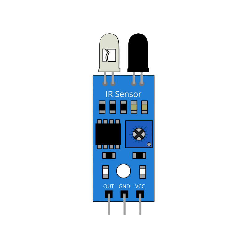
Pin Configuration
The IR sensor module typically has three or more pins. Below is the pin configuration for a common 3-pin IR sensor module:
| Pin | Name | Description |
|---|---|---|
| 1 | VCC | Power supply pin (3.3V to 5V) |
| 2 | GND | Ground pin |
| 3 | OUT | Output pin (Digital or Analog signal based on model) |
For modules with additional pins, such as an EN (Enable) pin or sensitivity adjustment, refer to the specific datasheet.
Usage Instructions
How to Use the IR Sensor in a Circuit
- Power the Sensor: Connect the VCC pin to a 3.3V or 5V power source and the GND pin to the ground.
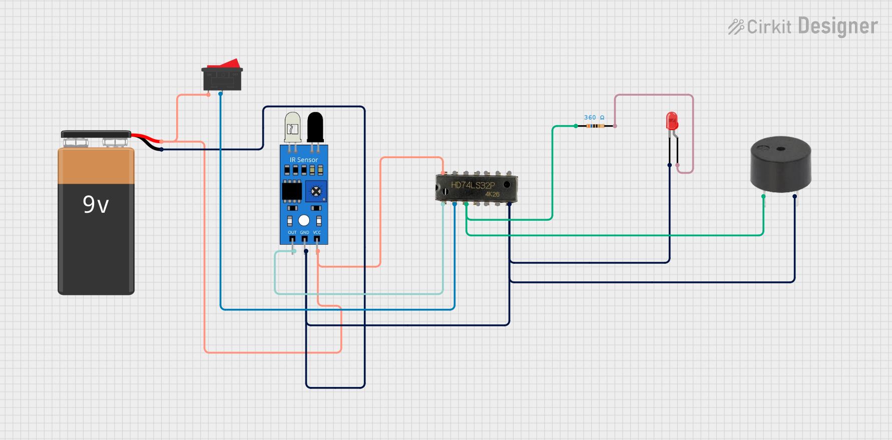
- Connect the Output: Connect the OUT pin to a microcontroller (e.g., Arduino) or directly to an LED/buzzer for basic testing.
- Adjust Sensitivity: If the module has a potentiometer, adjust it to set the detection range.
- Test the Sensor: Place an object within the detection range to observe the output signal.
Important Considerations and Best Practices
- Ambient Light Interference: IR sensors can be affected by sunlight or other strong light sources. Use them in controlled lighting conditions or shield the sensor.
- Reflective Surfaces: Highly reflective surfaces may cause inaccurate readings. Test the sensor with the intended materials.
- Power Supply: Ensure a stable power supply to avoid erratic behavior.
- Distance Calibration: Adjust the potentiometer (if available) to fine-tune the detection range for your application.
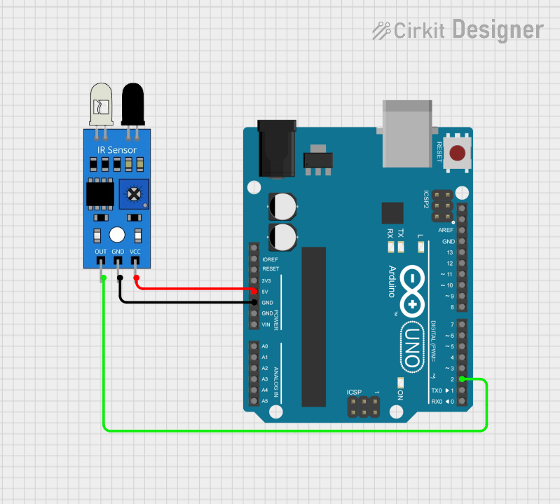
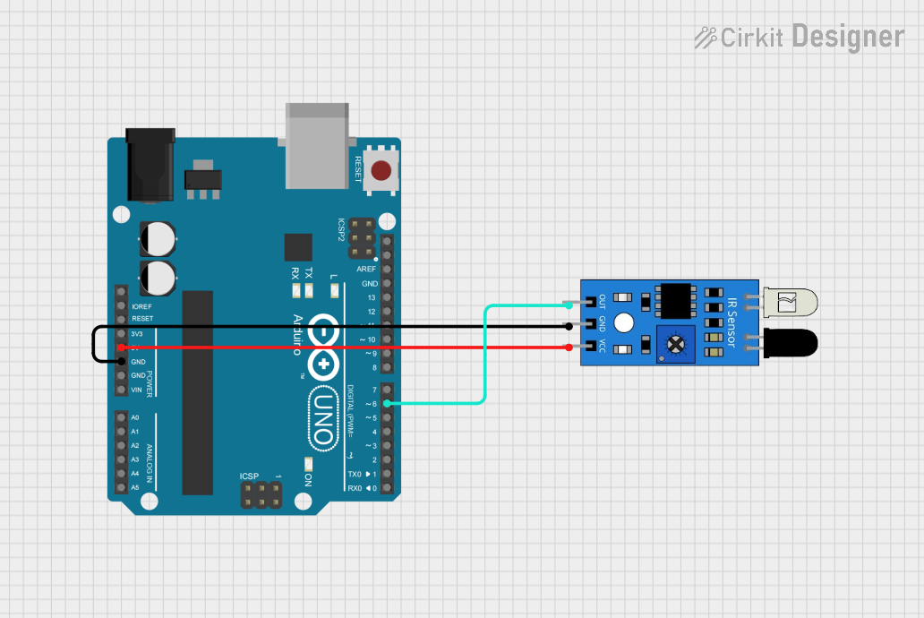
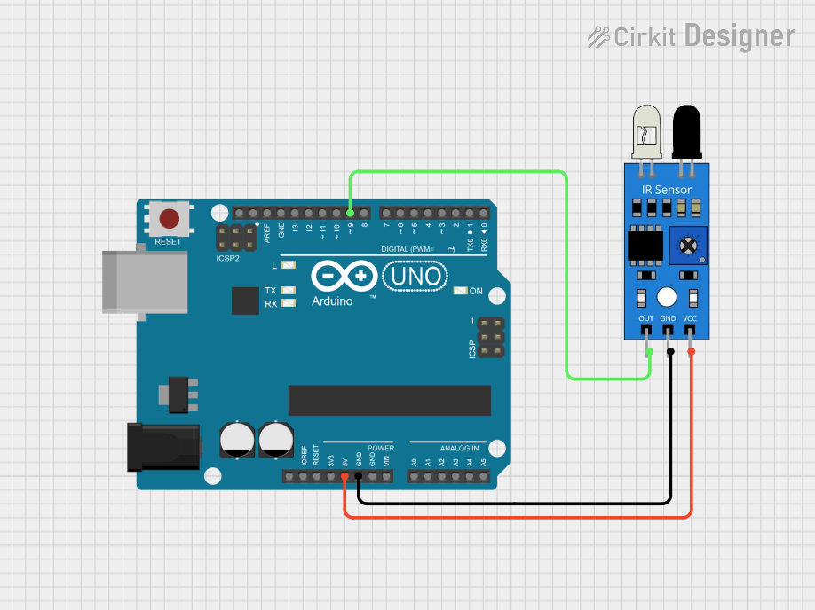
Example: Connecting an IR Sensor to an Arduino UNO
Below is an example of how to use an IR sensor with an Arduino UNO to detect an object and turn on an LED:
// Define pin connections
const int irSensorPin = 2;  // IR sensor output connected to digital pin 2
const int ledPin = 13;      // Built-in LED on Arduino

void setup() {
  pinMode(irSensorPin, INPUT);  // Set IR sensor pin as input
  pinMode(ledPin, OUTPUT);      // Set LED pin as output
  Serial.begin(9600);           // Initialize serial communication
}

void loop() {
  int sensorValue = digitalRead(irSensorPin);  // Read the IR sensor output

  if (sensorValue == LOW) {  // Object detected (LOW signal from sensor)
    digitalWrite(ledPin, HIGH);  // Turn on the LED
    Serial.println("Object detected!");
  } else {  // No object detected (HIGH signal from sensor)
    digitalWrite(ledPin, LOW);   // Turn off the LED
    Serial.println("No object detected.");
  }

  delay(100);  // Small delay for stability
}
Notes:
- The IR sensor output is typically LOW when an object is detected and HIGH otherwise. Verify this behavior for your specific module.
- Adjust the detection range using the potentiometer on the sensor module if necessary.
Troubleshooting and FAQs
Common Issues and Solutions
The sensor is not detecting objects:
- Ensure the sensor is powered correctly (check VCC and GND connections).
- Verify that the object is within the detection range.
- Adjust the potentiometer to increase sensitivity.
False triggers or erratic behavior:
- Check for ambient light interference and shield the sensor if needed.
- Ensure a stable power supply to the sensor module.
Output signal is not as expected:
- Confirm the wiring and pin connections.
- Test the sensor with a multimeter or oscilloscope to verify the output signal.
FAQs
Q: Can the IR sensor detect transparent objects?
A: IR sensors may struggle to detect transparent or translucent objects. Use a sensor specifically designed for such applications.
Q: How do I increase the detection range?
A: Adjust the potentiometer on the sensor module (if available). For fixed-range sensors, consider using a model with a longer detection range.
Q: Can I use the IR sensor outdoors?
A: While possible, outdoor use may result in reduced accuracy due to sunlight interference. Use an IR sensor with ambient light filtering for better performance.
Q: What is the difference between analog and digital IR sensors?
A: Analog IR sensors provide a continuous voltage output proportional to the distance of the object, while digital IR sensors output a HIGH or LOW signal based on a threshold distance.
By following this documentation, you can effectively integrate an IR sensor into your projects and troubleshoot common issues.