How to Use BT139 600: Examples, Pinouts, and Specs
Introduction
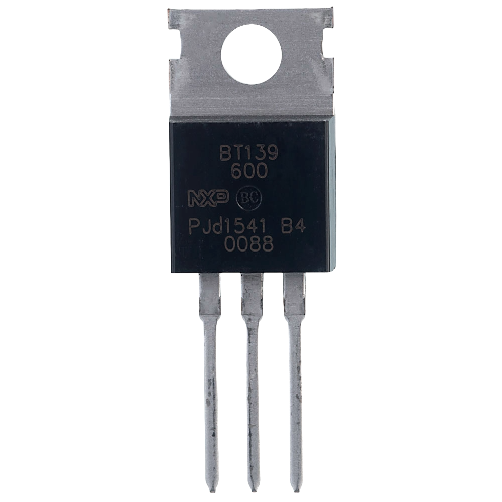
The BT139 600 is a triac (triode for alternating current) designed for controlling AC power in various applications. It is capable of handling a maximum voltage of 600V and a continuous current of up to 16A. This component is widely used in circuits requiring efficient switching and control of AC loads, such as light dimmers, motor speed controllers, and heating systems. Its robust design and reliable performance make it a popular choice for both industrial and consumer electronics.
Explore Projects Built with BT139 600


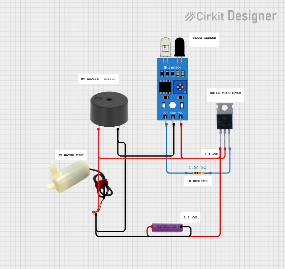
Explore Projects Built with BT139 600
Technical Specifications
Below are the key technical details of the BT139 600 triac:
| Parameter | Value |
|---|---|
| Maximum Voltage (VDRM) | 600V |
| Maximum Current (IT(RMS)) | 16A |
| Gate Trigger Voltage (VGT) | 1.5V (typical) |
| Gate Trigger Current (IGT) | 35mA (typical) |
| Holding Current (IH) | 25mA (typical) |
| Maximum Surge Current (ITSM) | 140A (non-repetitive, 20ms) |
| Operating Temperature Range | -40°C to +125°C |
| Package Type | TO-220 |
Pin Configuration and Descriptions
The BT139 600 comes in a TO-220 package with three pins. The pin configuration is as follows:
| Pin Number | Pin Name | Description |
|---|---|---|
| 1 | MT1 (Main Terminal 1) | Connected to one side of the AC load. |
| 2 | MT2 (Main Terminal 2) | Connected to the other side of the AC load. |
| 3 | Gate | Used to trigger the triac into conduction. |
Usage Instructions
How to Use the BT139 600 in a Circuit
Basic Circuit Setup:
- Connect the AC load between MT2 and the neutral line of the AC supply.
- Connect MT1 to the live line of the AC supply.
- Use a resistor to limit the current to the Gate pin. The resistor value is typically chosen to ensure the gate current exceeds the trigger current (IGT).
Gate Triggering:
- To turn the triac ON, apply a small current to the Gate pin. This can be achieved using a microcontroller, a transistor, or a manual switch.
- Once triggered, the triac will remain ON as long as the current through MT1 and MT2 remains above the holding current (IH).
Snubber Circuit:
- For inductive loads (e.g., motors), include a snubber circuit (a resistor and capacitor in series) across the triac to prevent voltage spikes that could damage the component.
Example: Controlling a Lamp with an Arduino UNO
Below is an example of how to use the BT139 600 to control an AC lamp with an Arduino UNO:
/*
  Example: Controlling an AC Lamp with BT139 600 and Arduino UNO
  Note: This example assumes the use of an optocoupler for isolation
  between the Arduino and the AC circuit. Always exercise caution
  when working with AC mains voltage.
*/

const int gatePin = 9; // Arduino pin connected to the Gate of the triac

void setup() {
  pinMode(gatePin, OUTPUT); // Set the gate pin as an output
}

void loop() {
  digitalWrite(gatePin, HIGH); // Turn ON the triac (lamp ON)
  delay(1000);                // Keep the lamp ON for 1 second
  digitalWrite(gatePin, LOW); // Turn OFF the triac (lamp OFF)
  delay(1000);                // Keep the lamp OFF for 1 second
}
Important Notes:
- Always use an optocoupler to isolate the Arduino from the high-voltage AC circuit.
- Ensure proper heat dissipation for the BT139 600 using a heatsink, especially for high-power loads.
- Verify the resistor value used for the Gate pin to avoid exceeding the gate current rating.
Troubleshooting and FAQs
Common Issues and Solutions
Triac Does Not Turn ON:
- Cause: Insufficient gate current.
- Solution: Check the resistor value connected to the Gate pin and ensure it allows enough current to exceed the gate trigger current (IGT).
Triac Turns OFF Unexpectedly:
- Cause: Load current drops below the holding current (IH).
- Solution: Ensure the load current remains above the holding current. For low-power loads, consider adding a parallel resistor to increase the current.
Triac Overheats:
- Cause: Excessive current or inadequate heat dissipation.
- Solution: Use a heatsink to dissipate heat effectively. Ensure the load current does not exceed the maximum rated current (IT(RMS)).
Voltage Spikes Damage the Triac:
- Cause: Inductive loads generating high voltage transients.
- Solution: Add a snubber circuit across the triac to suppress voltage spikes.
FAQs
Q: Can the BT139 600 be used for DC loads?
A: No, the BT139 600 is designed for AC loads. It relies on the zero-crossing of the AC waveform to turn OFF.Q: What is the purpose of the snubber circuit?
A: The snubber circuit protects the triac from voltage spikes caused by inductive loads, ensuring reliable operation.Q: How do I calculate the gate resistor value?
A: Use Ohm's Law: R = (Vtrigger - VGT) / IGT, where Vtrigger is the control voltage (e.g., 5V from Arduino).
By following these guidelines and best practices, you can effectively use the BT139 600 triac in your AC control applications.