
How to Use OpAmp Breakout: Examples, Pinouts, and Specs
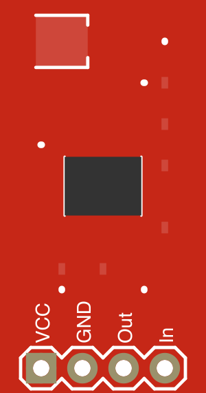
 Design with OpAmp Breakout in Cirkit Designer
Introduction
The OpAmp Breakout (Manufacturer Part ID: BOB-09816) by SparkFun Electronics is a compact and versatile breakout board designed to simplify the use of operational amplifiers (OpAmps) in prototyping and testing circuits. This breakout board provides easy access to the pins of an OpAmp, enabling quick and efficient circuit assembly. It is ideal for applications requiring signal amplification, filtering, or mathematical operations such as addition, subtraction, and integration.
Explore Projects Built with OpAmp Breakout
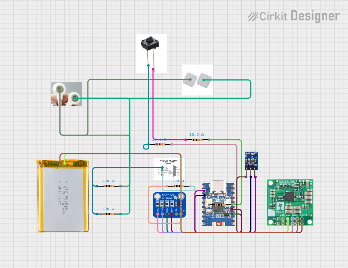 Open Project in Cirkit Designer
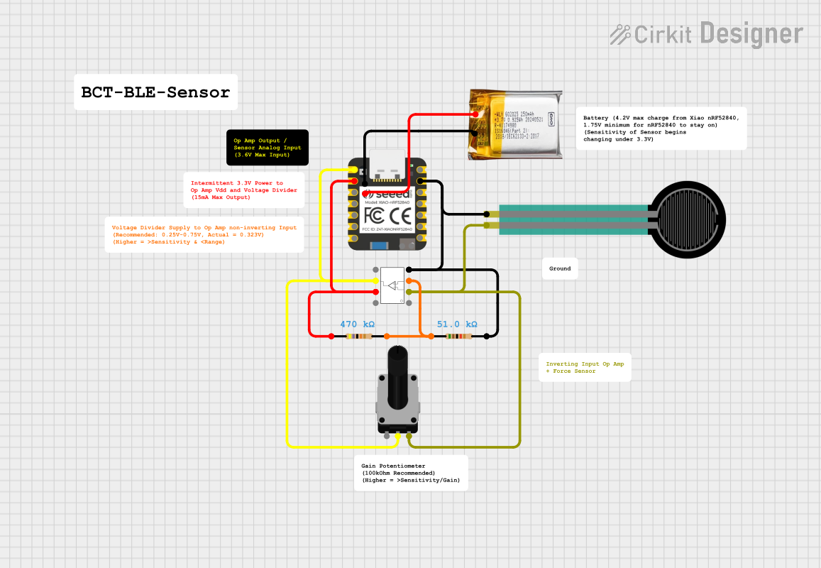 Open Project in Cirkit Designer
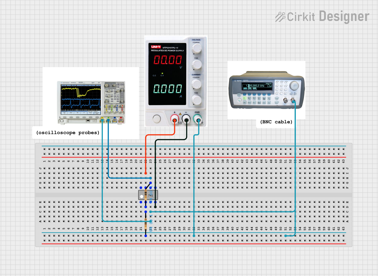 Open Project in Cirkit Designer
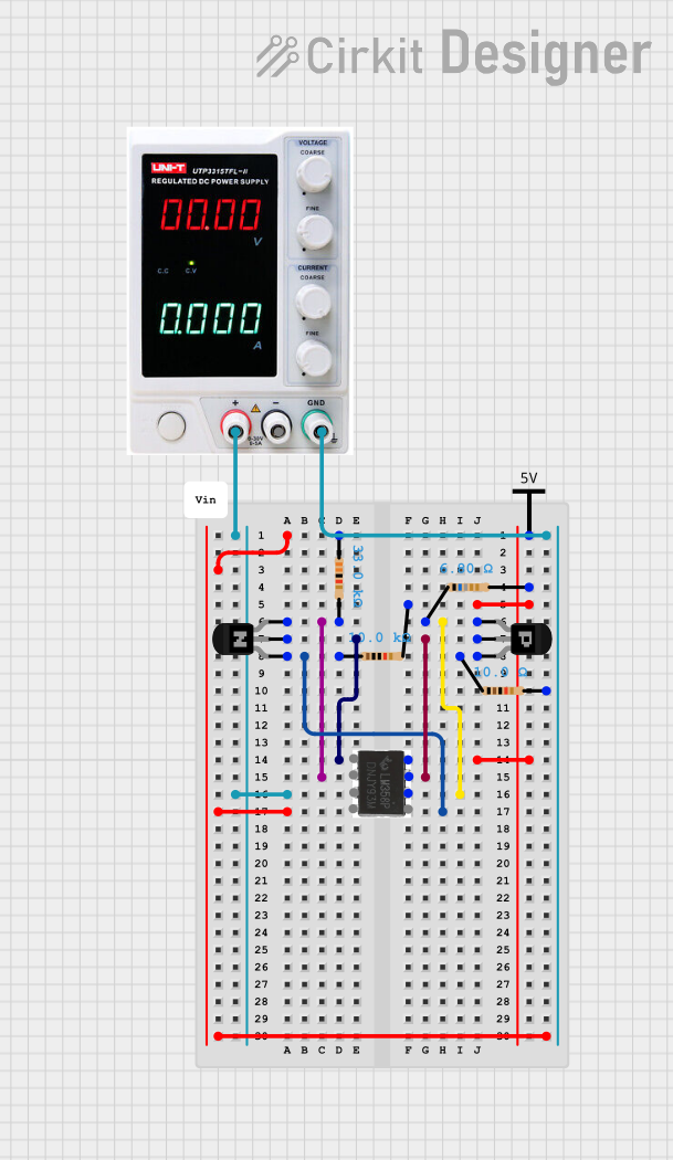 Open Project in Cirkit Designer
Explore Projects Built with OpAmp Breakout
Open Project in Cirkit DesignerOpen Project in Cirkit DesignerOpen Project in Cirkit DesignerOpen Project in Cirkit DesignerCommon Applications
- Signal amplification for sensors and audio signals
- Analog filters (low-pass, high-pass, band-pass)
- Voltage followers (buffer circuits)
- Differential amplifiers
- Mathematical operations in analog computing
Technical Specifications
Key Technical Details
- Manufacturer: SparkFun Electronics
- Part Number: BOB-09816
- Supported OpAmp ICs: Compatible with standard 8-pin DIP OpAmp ICs (e.g., LM358, TL081)
- Power Supply Voltage: ±3V to ±15V (depending on the OpAmp used)
- Input/Output Voltage Range: Determined by the OpAmp IC specifications
- PCB Dimensions: 1.0" x 1.0" (25.4mm x 25.4mm)
- Pre-soldered Components: None (user must solder the OpAmp and any additional components)
Pin Configuration and Descriptions
The breakout board provides access to all 8 pins of a standard OpAmp IC. Below is the pinout for a typical dual OpAmp IC (e.g., LM358):
| Pin Number | Pin Name | Description |
|---|---|---|
| 1 | Output 1 | Output of the first OpAmp |
| 2 | Inverting Input 1 | Inverting input of the first OpAmp |
| 3 | Non-Inverting Input 1 | Non-inverting input of the first OpAmp |
| 4 | V- (GND) | Negative power supply or ground |
| 5 | Non-Inverting Input 2 | Non-inverting input of the second OpAmp |
| 6 | Inverting Input 2 | Inverting input of the second OpAmp |
| 7 | Output 2 | Output of the second OpAmp |
| 8 | V+ | Positive power supply |
Note: The pinout may vary depending on the specific OpAmp IC used. Always refer to the datasheet of the OpAmp IC for accurate pin descriptions.
Usage Instructions
How to Use the OpAmp Breakout
- Solder the OpAmp IC: Place the OpAmp IC into the 8-pin DIP socket on the breakout board and solder it securely.
- Connect Power Supply: Attach the positive voltage (V+) and ground (V-) to the corresponding pins on the breakout board. Ensure the voltage levels match the OpAmp IC's specifications.
- Connect Input and Output: Use the breakout pins to connect the inverting and non-inverting inputs, as well as the output, to your circuit.
- Add External Components: Depending on your application, solder additional components (e.g., resistors, capacitors) to the breakout board to configure the OpAmp for your desired functionality.
Important Considerations
- Power Supply: Ensure the power supply voltage is within the range specified for the OpAmp IC. Exceeding this range may damage the IC.
- Bypass Capacitors: For stable operation, add bypass capacitors (e.g., 0.1µF ceramic capacitors) between the power supply pins (V+ and V-) and ground.
- Input Voltage Range: Verify that the input voltage levels are within the acceptable range for the OpAmp IC to avoid distortion or damage.
- Heat Management: While most OpAmps do not generate significant heat, ensure proper ventilation if used in high-power applications.
Example: Connecting to an Arduino UNO
Below is an example of using the OpAmp Breakout with an LM358 OpAmp to amplify an analog signal from a sensor and read it with an Arduino UNO.
Circuit Diagram
- Connect the sensor output to the non-inverting input (Pin 3) of the LM358.
- Use a resistor divider to set the gain of the OpAmp.
- Connect the OpAmp output (Pin 1) to an analog input pin (e.g., A0) on the Arduino UNO.
Arduino Code
// Example code to read an amplified signal from the OpAmp Breakout
// and display the value on the Serial Monitor.

const int analogPin = A0; // Analog pin connected to OpAmp output
int sensorValue = 0;      // Variable to store the analog reading

void setup() {
  Serial.begin(9600); // Initialize serial communication at 9600 baud
}

void loop() {
  sensorValue = analogRead(analogPin); // Read the analog value
  Serial.print("Amplified Signal: ");
  Serial.println(sensorValue); // Print the value to the Serial Monitor
  delay(500); // Wait for 500ms before the next reading
}
Note: Adjust the resistor values in the circuit to achieve the desired gain for your application.
Troubleshooting and FAQs
Common Issues and Solutions
No Output Signal
- Cause: Incorrect power supply connections or insufficient voltage.
- Solution: Verify the power supply connections and ensure the voltage matches the OpAmp IC's requirements.
Distorted Output Signal
- Cause: Input voltage exceeds the OpAmp's input range or incorrect gain configuration.
- Solution: Check the input voltage levels and adjust the gain by modifying the resistor values.
OpAmp Overheating
- Cause: Excessive current draw or incorrect power supply voltage.
- Solution: Ensure the power supply voltage is within the specified range and check for short circuits.
Unstable Operation
- Cause: Lack of bypass capacitors or poor grounding.
- Solution: Add bypass capacitors (e.g., 0.1µF) near the power supply pins and ensure a solid ground connection.
FAQs
Can I use this breakout board with single-supply OpAmps?
Yes, the breakout board supports single-supply OpAmps. Connect the V- pin to ground and provide a positive voltage to the V+ pin.What is the maximum frequency this breakout board can handle?
The frequency response depends on the OpAmp IC used. Refer to the datasheet of your specific OpAmp for details on bandwidth and slew rate.Do I need to solder the OpAmp IC permanently?
No, you can use an 8-pin DIP socket to make the OpAmp removable for easy replacement or testing.Can I use this breakout board for audio applications?
Yes, the OpAmp Breakout is suitable for audio signal amplification and filtering, provided the OpAmp IC used has appropriate specifications for audio frequencies.
By following this documentation, you can effectively utilize the SparkFun OpAmp Breakout (BOB-09816) for a wide range of analog circuit applications.