Cirkit Designer Logo
Cirkit Designer
Your all-in-one circuit design IDE
Home / 
Component Documentation

How to Use Touch Sensor Module: Examples, Pinouts, and Specs

Image of Touch Sensor Module
Cirkit Designer LogoDesign with Touch Sensor Module in Cirkit Designer

Introduction

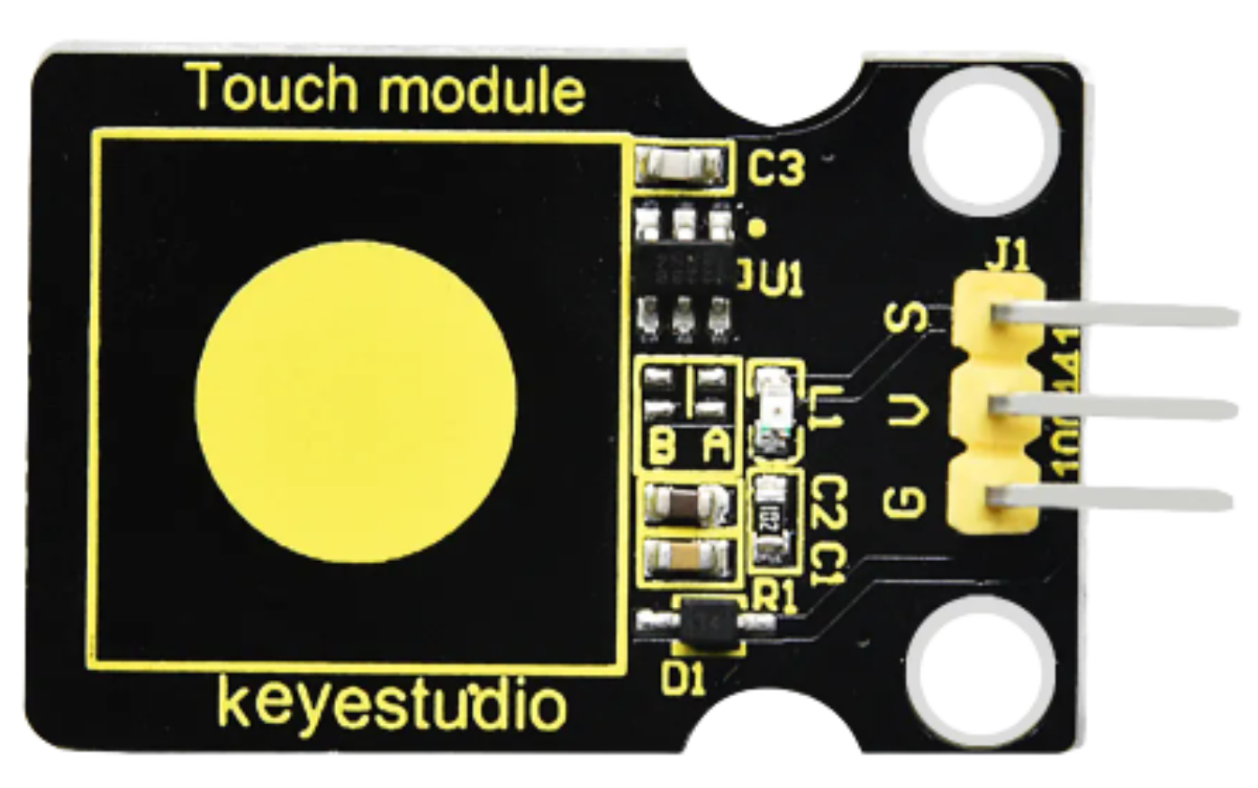
The Keyestudio Touch Sensor Module (KS0031) is a compact and reliable device designed to detect touch or proximity. It is widely used in user interfaces to enable interaction with electronic devices, replacing traditional mechanical buttons. The module is based on capacitive touch sensing technology, which ensures high sensitivity and durability. Its simple design and ease of integration make it a popular choice for hobbyists, students, and professionals.

Explore Projects Built with Touch Sensor Module

Use Cirkit Designer to design, explore, and prototype these projects online. Some projects support real-time simulation. Click "Open Project" to start designing instantly!
Arduino Nano-Based Wearable Gesture Control Interface with Bluetooth Connectivity
Image of spine: A project utilizing Touch Sensor Module in a practical application
This is a battery-powered sensor system with Bluetooth communication, featuring an Arduino Nano for control, an MPU-6050 for motion sensing, and an HC-05 module for wireless data transmission. It includes a vibration motor for haptic feedback, a flex resistor as an additional sensor, and a piezo speaker and LED for alerts or status indication.
Cirkit Designer LogoOpen Project in Cirkit Designer
Arduino Mega 2560 Bluetooth-Controlled Touch-Activated Vibration Motor System
Image of circuitcycle: A project utilizing Touch Sensor Module in a practical application
This circuit is a touch-activated feedback system that uses an Arduino Mega 2560 to control multiple vibration motors and a buzzer. Touch sensors (TTP233) are used to detect user input, which then triggers the corresponding vibration motor and buzzer via the Arduino. Additionally, an HC-05 Bluetooth module is included for wireless communication.
Cirkit Designer LogoOpen Project in Cirkit Designer
ESP8266 NodeMCU-Based Environmental Monitoring System with SIM900A GSM Communication
Image of IOE: A project utilizing Touch Sensor Module in a practical application
This is a sensor-based data acquisition system with GSM communication capability. It uses an ESP8266 NodeMCU to collect environmental data from a DHT22 sensor and light levels from an LDR, as well as distance measurements from an HC-SR04 ultrasonic sensor. The SIM900A GSM module enables the system to transmit the collected data over a cellular network.
Cirkit Designer LogoOpen Project in Cirkit Designer
Gesture-Controlled Wheelchair with Arduino UNO, Arduino Nano, and HC-05 Bluetooth Modules
Image of Gesture Control Wheelchair: A project utilizing Touch Sensor Module in a practical application
This circuit features an Arduino Nano interfaced with an InvenSense MPU6050 accelerometer/gyroscope for motion sensing and an HC-05 Bluetooth module for wireless communication. The Arduino Nano processes the MPU6050 data to interpret gestures and sends corresponding commands via Bluetooth. Additionally, an Arduino UNO is connected to an L298N motor driver to control two DC motors, receiving commands from a separate HC-05 module, likely for remote maneuvering of a vehicle or robotic platform.
Cirkit Designer LogoOpen Project in Cirkit Designer

Explore Projects Built with Touch Sensor Module

Use Cirkit Designer to design, explore, and prototype these projects online. Some projects support real-time simulation. Click "Open Project" to start designing instantly!
Image of spine: A project utilizing Touch Sensor Module in a practical application
Arduino Nano-Based Wearable Gesture Control Interface with Bluetooth Connectivity
This is a battery-powered sensor system with Bluetooth communication, featuring an Arduino Nano for control, an MPU-6050 for motion sensing, and an HC-05 module for wireless data transmission. It includes a vibration motor for haptic feedback, a flex resistor as an additional sensor, and a piezo speaker and LED for alerts or status indication.
Cirkit Designer LogoOpen Project in Cirkit Designer
Image of circuitcycle: A project utilizing Touch Sensor Module in a practical application
Arduino Mega 2560 Bluetooth-Controlled Touch-Activated Vibration Motor System
This circuit is a touch-activated feedback system that uses an Arduino Mega 2560 to control multiple vibration motors and a buzzer. Touch sensors (TTP233) are used to detect user input, which then triggers the corresponding vibration motor and buzzer via the Arduino. Additionally, an HC-05 Bluetooth module is included for wireless communication.
Cirkit Designer LogoOpen Project in Cirkit Designer
Image of IOE: A project utilizing Touch Sensor Module in a practical application
ESP8266 NodeMCU-Based Environmental Monitoring System with SIM900A GSM Communication
This is a sensor-based data acquisition system with GSM communication capability. It uses an ESP8266 NodeMCU to collect environmental data from a DHT22 sensor and light levels from an LDR, as well as distance measurements from an HC-SR04 ultrasonic sensor. The SIM900A GSM module enables the system to transmit the collected data over a cellular network.
Cirkit Designer LogoOpen Project in Cirkit Designer
Image of Gesture Control Wheelchair: A project utilizing Touch Sensor Module in a practical application
Gesture-Controlled Wheelchair with Arduino UNO, Arduino Nano, and HC-05 Bluetooth Modules
This circuit features an Arduino Nano interfaced with an InvenSense MPU6050 accelerometer/gyroscope for motion sensing and an HC-05 Bluetooth module for wireless communication. The Arduino Nano processes the MPU6050 data to interpret gestures and sends corresponding commands via Bluetooth. Additionally, an Arduino UNO is connected to an L298N motor driver to control two DC motors, receiving commands from a separate HC-05 module, likely for remote maneuvering of a vehicle or robotic platform.
Cirkit Designer LogoOpen Project in Cirkit Designer

Common Applications and Use Cases

  • Touch-sensitive buttons for home appliances
  • Interactive displays and kiosks
  • Wearable devices
  • Proximity detection in IoT projects
  • Capacitive touch-based lighting controls

Technical Specifications

The following table outlines the key technical details of the Keyestudio Touch Sensor Module (KS0031):

Parameter Specification
Operating Voltage 2.0V to 5.5V
Operating Current < 20µA (low power consumption)
Output Type Digital (High/Low)
Response Time < 60ms (fast response)
Interface Type 3-pin (VCC, GND, OUT)
Dimensions 15mm x 24mm
Touch Sensitivity Adjustable via onboard configuration

Pin Configuration and Descriptions

The module has a 3-pin interface, as described in the table below:

Pin Name Description
1 VCC Power supply pin. Connect to a voltage source (2.0V to 5.5V).
2 GND Ground pin. Connect to the ground of the circuit.
3 OUT Digital output pin. Outputs HIGH when touch is detected, LOW otherwise.

Usage Instructions

How to Use the Component in a Circuit

  1. Power the Module: Connect the VCC pin to a 3.3V or 5V power source and the GND pin to the ground.
  2. Connect the Output: Attach the OUT pin to a digital input pin of your microcontroller or other logic circuit.
  3. Touch Detection: When the touch-sensitive area of the module is touched, the OUT pin will output a HIGH signal. When no touch is detected, the OUT pin will output a LOW signal.

Important Considerations and Best Practices

  • Power Supply: Ensure the power supply voltage is within the specified range (2.0V to 5.5V) to avoid damaging the module.
  • Debouncing: If the module is used in a noisy environment, consider implementing software debouncing to filter out false triggers.
  • Sensitivity Adjustment: Some versions of the module allow sensitivity adjustment via onboard components. Refer to the manufacturer's datasheet for details.
  • Avoid Interference: Keep the module away from high-frequency noise sources to maintain reliable operation.

Example: Connecting to an Arduino UNO

Below is an example of how to connect and use the Keyestudio Touch Sensor Module with an Arduino UNO:

Circuit Diagram

  • Connect the VCC pin of the module to the 5V pin on the Arduino.
  • Connect the GND pin of the module to the GND pin on the Arduino.
  • Connect the OUT pin of the module to digital pin 2 on the Arduino.

Arduino Code

// Define the pin connected to the OUT pin of the touch sensor
const int touchSensorPin = 2;

// Define the onboard LED pin (for feedback)
const int ledPin = 13;

void setup() {
  // Initialize the touch sensor pin as an input
  pinMode(touchSensorPin, INPUT);

  // Initialize the LED pin as an output
  pinMode(ledPin, OUTPUT);

  // Start the serial communication for debugging
  Serial.begin(9600);
}

void loop() {
  // Read the state of the touch sensor
  int touchState = digitalRead(touchSensorPin);

  // If the sensor is touched, turn on the LED
  if (touchState == HIGH) {
    digitalWrite(ledPin, HIGH); // Turn on the LED
    Serial.println("Touch detected!"); // Print message to serial monitor
  } else {
    digitalWrite(ledPin, LOW); // Turn off the LED
    Serial.println("No touch detected."); // Print message to serial monitor
  }

  // Add a small delay to avoid spamming the serial monitor
  delay(100);
}

Troubleshooting and FAQs

Common Issues and Solutions

  1. The module does not respond to touch.

    • Solution: Verify that the power supply voltage is within the specified range (2.0V to 5.5V).
    • Solution: Check all connections to ensure they are secure and correctly wired.
    • Solution: Ensure the touch-sensitive area is clean and free from debris.
  2. False triggers or inconsistent behavior.

    • Solution: Keep the module away from sources of electromagnetic interference (e.g., motors, high-frequency circuits).
    • Solution: Add a pull-down resistor to the OUT pin if necessary to stabilize the signal.
  3. The output signal is not detected by the microcontroller.

    • Solution: Confirm that the OUT pin is connected to a digital input pin on the microcontroller.
    • Solution: Check the microcontroller's pin configuration and ensure it is set as an input.

FAQs

Q: Can the module detect proximity without direct touch?
A: Yes, the module can detect proximity depending on the sensitivity settings and environmental conditions.

Q: Is the module waterproof?
A: No, the module is not waterproof. Avoid exposing it to moisture or liquids.

Q: Can I use this module with a 3.3V microcontroller?
A: Yes, the module operates within a voltage range of 2.0V to 5.5V, making it compatible with 3.3V systems.

Q: How do I adjust the sensitivity of the module?
A: Some versions of the module include an onboard potentiometer or jumper for sensitivity adjustment. Refer to the manufacturer's datasheet for specific instructions.