How to Use Bottom LM7805 PCB Board: Examples, Pinouts, and Specs
Introduction
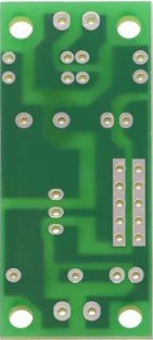
The Bottom LM7805 PCB Board is a compact printed circuit board designed to house and connect the LM7805 voltage regulator. The LM7805 is a popular linear voltage regulator that provides a stable 5V DC output from a higher DC input voltage, typically ranging from 7V to 35V. This PCB simplifies the integration of the LM7805 into electronic projects by providing a pre-designed layout with input/output terminals and optional components for filtering and stability.
Explore Projects Built with Bottom LM7805 PCB Board


Explore Projects Built with Bottom LM7805 PCB Board
Common Applications and Use Cases
- Power supply circuits for microcontrollers, sensors, and modules
- Voltage regulation for battery-powered devices
- Prototyping and DIY electronics projects
- Providing a stable 5V output for Arduino, Raspberry Pi, or other development boards
Technical Specifications
The Bottom LM7805 PCB Board is designed to support the LM7805 voltage regulator and its associated components. Below are the key technical details:
General Specifications
- Input Voltage Range: 7V to 35V DC
- Output Voltage: 5V DC (regulated)
- Maximum Output Current: 1A to 1.5A (depending on heat dissipation)
- PCB Dimensions: Typically compact (e.g., 25mm x 30mm, varies by manufacturer)
- Optional Components: Capacitor slots for input and output filtering
Pin Configuration and Descriptions
The LM7805 voltage regulator has three pins, which are connected to the PCB as follows:
| Pin Number | Pin Name | Description |
|---|---|---|
| 1 | Input (IN) | Connects to the unregulated DC input voltage. |
| 2 | Ground (GND) | Common ground for input and output. |
| 3 | Output (OUT) | Provides the regulated 5V DC output. |
The PCB typically includes labeled terminals or solder pads for easy connection to external components.
Recommended Capacitor Values
| Capacitor Position | Recommended Value | Purpose |
|---|---|---|
| Input Capacitor | 0.33µF to 1µF | Reduces input voltage noise and ripples. |
| Output Capacitor | 0.1µF to 1µF | Improves output stability and reduces noise. |
Usage Instructions
How to Use the Bottom LM7805 PCB Board in a Circuit
Prepare the Components:
- Obtain an LM7805 voltage regulator and the recommended capacitors (0.33µF for input and 0.1µF for output).
- Optionally, include a heatsink for the LM7805 if the load current exceeds 500mA.
Assemble the PCB:
- Solder the LM7805 regulator onto the PCB, ensuring the correct orientation of the pins.
- Solder the input and output capacitors in their designated slots on the PCB.
Connect the Input Voltage:
- Attach the unregulated DC input voltage (7V to 35V) to the input terminal or solder pad.
- Ensure the polarity is correct to avoid damaging the regulator.
Connect the Output Load:
- Connect the device or circuit requiring a 5V supply to the output terminal or solder pad.
Power On:
- Apply the input voltage and verify the output voltage using a multimeter. It should read approximately 5V DC.
Important Considerations and Best Practices
- Heat Dissipation: The LM7805 can generate significant heat under high current loads. Use a heatsink or ensure proper ventilation to prevent overheating.
- Input Voltage Range: Ensure the input voltage is at least 2V higher than the desired output voltage (minimum 7V for a 5V output).
- Capacitor Placement: Place the capacitors as close as possible to the regulator pins for optimal performance.
- Polarity Protection: Consider adding a diode in series with the input to protect against reverse polarity.
Example: Connecting to an Arduino UNO
The Bottom LM7805 PCB Board can be used to power an Arduino UNO from a 12V DC input. Below is an example circuit and Arduino code to blink an LED:
Circuit Connections
- Connect a 12V DC input to the PCB's input terminal.
- Connect the PCB's 5V output to the Arduino UNO's 5V pin.
- Connect the PCB's ground to the Arduino UNO's GND pin.
Arduino Code
// Simple LED Blink Example
// This code blinks an LED connected to pin 13 of the Arduino UNO.

void setup() {
  pinMode(13, OUTPUT); // Set pin 13 as an output pin
}

void loop() {
  digitalWrite(13, HIGH); // Turn the LED on
  delay(1000);            // Wait for 1 second
  digitalWrite(13, LOW);  // Turn the LED off
  delay(1000);            // Wait for 1 second
}
Troubleshooting and FAQs
Common Issues and Solutions
No Output Voltage:
- Cause: Incorrect input voltage or reversed polarity.
- Solution: Verify the input voltage is within the specified range (7V to 35V) and check the polarity.
Overheating:
- Cause: High current load or insufficient heat dissipation.
- Solution: Add a heatsink to the LM7805 or reduce the load current.
Output Voltage Fluctuations:
- Cause: Missing or improperly placed capacitors.
- Solution: Ensure the input and output capacitors are soldered close to the regulator pins.
Damaged Regulator:
- Cause: Input voltage exceeds 35V or reverse polarity.
- Solution: Replace the LM7805 and add a diode for polarity protection.
FAQs
Q1: Can I use the Bottom LM7805 PCB Board with an AC input?
A1: No, the LM7805 requires a DC input. If using an AC source, you must first rectify and filter it to obtain a DC voltage.
Q2: What is the maximum current the LM7805 can provide?
A2: The LM7805 can provide up to 1.5A, but this depends on proper heat dissipation. Without a heatsink, the maximum current may be lower.
Q3: Can I use this PCB to power a 3.3V device?
A3: No, the LM7805 outputs a fixed 5V. For 3.3V devices, use a regulator like the LM7833 or a buck converter.
Q4: Do I need to use both input and output capacitors?
A4: Yes, for optimal performance and stability, it is recommended to use both capacitors as specified in the datasheet.