How to Use SparkFun Spectral Sensor: Examples, Pinouts, and Specs
Introduction
The SparkFun Spectral Sensor (AS7343) is a highly versatile and precise light sensor designed to detect and measure light across 14 different spectral channels. Manufactured by SparkFun, this sensor is based on the AS7343 IC, which enables spectral analysis of materials by capturing light intensity at specific wavelengths. It is ideal for applications requiring color analysis, material identification, and environmental monitoring.
Explore Projects Built with SparkFun Spectral Sensor


Explore Projects Built with SparkFun Spectral Sensor
Common Applications and Use Cases
- Color matching and calibration
- Material analysis and identification
- Ambient light sensing
- Agricultural monitoring (e.g., plant health analysis)
- Industrial quality control
- Environmental monitoring and research
Technical Specifications
The AS7343 spectral sensor offers a wide range of features and capabilities. Below are the key technical details:
Key Technical Details
- Operating Voltage: 1.8V (core) and 3.3V (I/O)
- Communication Interface: I²C (up to 1 MHz)
- Spectral Channels: 14 channels (UV, visible, and near-infrared)
- Spectral Range: 350 nm to 1000 nm
- Measurement Modes: Single-shot or continuous
- Integration Time: Configurable (2.78 ms to 711 ms)
- Current Consumption:
- Active mode: ~200 µA
- Sleep mode: ~2 µA
- Package: 20-pin LGA
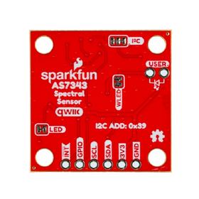
Pin Configuration and Descriptions
The AS7343 sensor is typically mounted on a breakout board by SparkFun. Below is the pin configuration for the breakout board:
| Pin Name | Type | Description |
|---|---|---|
| VIN | Power Input | Power supply input (3.3V recommended). |
| GND | Ground | Ground connection. |
| SDA | I²C Data | Serial data line for I²C communication. |
| SCL | I²C Clock | Serial clock line for I²C communication. |
| INT | Output | Interrupt pin, signals when a measurement is ready or an event occurs. |
| RST | Input | Reset pin, used to reset the sensor. |
| ADDR | Input | I²C address selection pin (connect to GND or VCC to set the address). |
Usage Instructions
The SparkFun Spectral Sensor (AS7343) is easy to integrate into a circuit and communicate with using the I²C protocol. Below are the steps to use the sensor effectively:
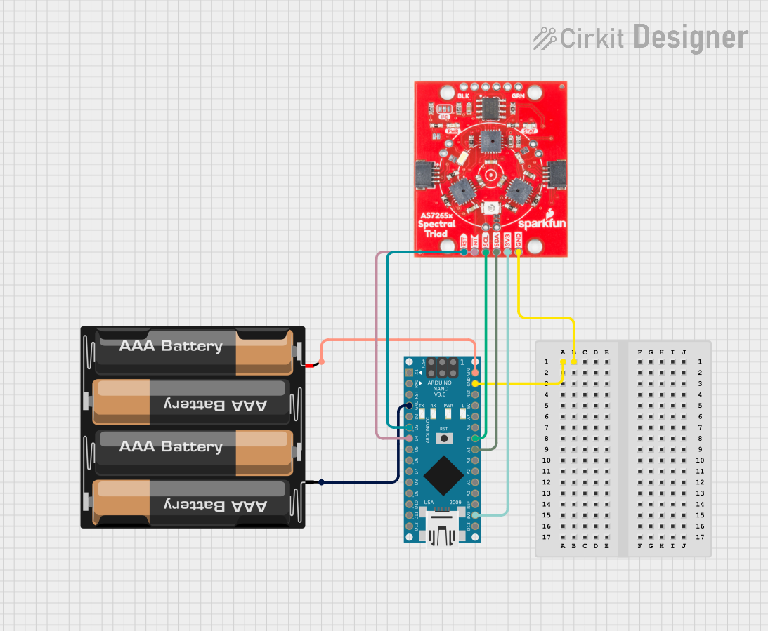
Connecting the Sensor
- Power the Sensor: Connect the VIN pin to a 3.3V power source and GND to ground.
- I²C Communication: Connect the SDA and SCL pins to the corresponding I²C pins on your microcontroller (e.g., Arduino UNO).
- Interrupt Pin (Optional): Connect the INT pin to a GPIO pin on your microcontroller if you want to use interrupts.
- Reset Pin (Optional): Connect the RST pin to a GPIO pin or leave it unconnected if not needed.
- I²C Address Selection: Use the ADDR pin to set the I²C address (connect to GND or VCC).
Arduino Example Code
Below is an example of how to use the AS7343 with an Arduino UNO. This code reads spectral data from the sensor and prints it to the Serial Monitor.
#include <Wire.h>

// I²C address of the AS7343 sensor
#define AS7343_I2C_ADDR 0x39

void setup() {
  Serial.begin(9600); // Initialize Serial Monitor
  Wire.begin();       // Initialize I²C communication

  // Initialize the AS7343 sensor
  if (!initializeAS7343()) {
    Serial.println("Failed to initialize AS7343 sensor!");
    while (1); // Halt execution if initialization fails
  }

  Serial.println("AS7343 sensor initialized successfully.");
}

void loop() {
  // Read and print spectral data
  readSpectralData();
  delay(1000); // Wait 1 second before the next reading
}

bool initializeAS7343() {
  Wire.beginTransmission(AS7343_I2C_ADDR);
  Wire.write(0x80); // Example: Write to a control register
  Wire.write(0x01); // Example: Enable the sensor
  return (Wire.endTransmission() == 0); // Check if the transmission was successful
}

void readSpectralData() {
  Wire.beginTransmission(AS7343_I2C_ADDR);
  Wire.write(0x94); // Example: Register address for spectral data
  Wire.endTransmission();

  Wire.requestFrom(AS7343_I2C_ADDR, 14); // Request 14 bytes of spectral data
  if (Wire.available() == 14) {
    Serial.println("Spectral Data:");
    for (int i = 0; i < 14; i++) {
      uint8_t data = Wire.read();
      Serial.print("Channel ");
      Serial.print(i + 1);
      Serial.print(": ");
      Serial.println(data);
    }
  } else {
    Serial.println("Failed to read spectral data.");
  }
}
Important Considerations and Best Practices
- Power Supply: Ensure the sensor is powered with a stable 3.3V supply. Avoid exceeding the voltage limits.
- I²C Pull-Up Resistors: Use appropriate pull-up resistors (typically 4.7 kΩ) on the SDA and SCL lines if not already present on the breakout board.
- Integration Time: Adjust the integration time based on the lighting conditions to avoid saturation or underexposure.
- Interrupts: Use the INT pin to optimize data acquisition in time-sensitive applications.
Troubleshooting and FAQs
Common Issues and Solutions
Sensor Not Detected on I²C Bus:
- Ensure the correct I²C address is used (default: 0x39).
- Check the wiring and ensure SDA and SCL are connected properly.
- Verify that pull-up resistors are present on the I²C lines.
Incorrect or No Spectral Data:
- Confirm that the sensor is initialized correctly.
- Check the integration time and gain settings to ensure proper measurements.
- Verify that the light source is within the sensor's spectral range (350 nm to 1000 nm).
Interrupt Pin Not Working:
- Ensure the INT pin is connected to a GPIO pin on the microcontroller.
- Verify that interrupts are enabled in the sensor's configuration.
FAQs
Q: Can the AS7343 measure UV light?
A: Yes, the AS7343 can measure light in the UV range starting from 350 nm.
Q: What is the maximum I²C speed supported?
A: The AS7343 supports I²C communication speeds of up to 1 MHz.
Q: Can I use the AS7343 with a 5V microcontroller?
A: Yes, but you must use a logic level shifter to convert the 5V I²C signals to 3.3V.
Q: How do I adjust the integration time?
A: The integration time can be configured by writing to the appropriate registers via I²C. Refer to the AS7343 datasheet for details.
Q: Is the sensor affected by ambient temperature?
A: The AS7343 is designed to operate within a temperature range of -40°C to +85°C. However, extreme temperatures may slightly affect performance.