Cirkit Designer Logo
Cirkit Designer
Your all-in-one circuit design IDE
Home / 
Component Documentation

How to Use WiFi LoRa 32(V3): Examples, Pinouts, and Specs

Image of WiFi LoRa 32(V3)
Cirkit Designer LogoDesign with WiFi LoRa 32(V3) in Cirkit Designer

Introduction

The WiFi LoRa 32 (V3) is a versatile development board manufactured by Heltec, identified by the part ID wL32v3. This board combines WiFi and LoRa technologies, leveraging the powerful ESP32 microcontroller. It is designed for Internet of Things (IoT) applications that require both long-range communication and internet connectivity. The integration of WiFi and LoRa makes it ideal for a wide range of applications, including remote sensing, smart agriculture, asset tracking, and more.

Explore Projects Built with WiFi LoRa 32(V3)

Use Cirkit Designer to design, explore, and prototype these projects online. Some projects support real-time simulation. Click "Open Project" to start designing instantly!
ESP32 and LoRa SX1278 Based Wireless Communication Module
Image of Esp 32 as Receiver or Sender: A project utilizing WiFi LoRa 32(V3) in a practical application
This circuit integrates an ESP32 microcontroller with a LoRa Ra-02 SX1278 module to enable long-range wireless communication. The ESP32 handles the control and data processing, while the LoRa module provides the communication link. The connections include SPI interface and control signals between the ESP32 and the LoRa module, as well as shared power and ground lines.
Cirkit Designer LogoOpen Project in Cirkit Designer
WiFi LoRa Environmental Monitoring System with INMP441 Mic and Multiple Sensors
Image of ba_sensing: A project utilizing WiFi LoRa 32(V3) in a practical application
This circuit is a solar-powered environmental monitoring system that uses a WiFi LoRa 32V3 microcontroller to collect data from various sensors, including a microphone, UV light sensor, air quality sensor, and temperature/humidity/pressure sensor. The collected data is processed and transmitted via LoRa communication, making it suitable for remote environmental data logging and monitoring applications.
Cirkit Designer LogoOpen Project in Cirkit Designer
ESP32-Based LoRa Communication Module
Image of Receptor_Proyect_Of_Grade: A project utilizing WiFi LoRa 32(V3) in a practical application
This circuit integrates an ESP32 microcontroller with a LoRa Ra-02 SX1278 module for long-range wireless communication. The ESP32's digital pins are connected to the LoRa module's SPI interface (MOSI, MISO, SCK, NSS) and control lines (RST, DI00) to enable data transmission and reception. The circuit is likely designed for IoT applications requiring low-power, wide-area network connectivity.
Cirkit Designer LogoOpen Project in Cirkit Designer
ESP32 and LoRa Communication Module for IoT Applications
Image of ESP32 LoRa: A project utilizing WiFi LoRa 32(V3) in a practical application
This circuit integrates an ESP32 microcontroller with a LoRa module for wireless communication, powered by an MB102 breadboard power supply. The ESP32 handles the control signals and data exchange with the LoRa module, enabling long-range, low-power data transmission.
Cirkit Designer LogoOpen Project in Cirkit Designer

Explore Projects Built with WiFi LoRa 32(V3)

Use Cirkit Designer to design, explore, and prototype these projects online. Some projects support real-time simulation. Click "Open Project" to start designing instantly!
Image of Esp 32 as Receiver or Sender: A project utilizing WiFi LoRa 32(V3) in a practical application
ESP32 and LoRa SX1278 Based Wireless Communication Module
This circuit integrates an ESP32 microcontroller with a LoRa Ra-02 SX1278 module to enable long-range wireless communication. The ESP32 handles the control and data processing, while the LoRa module provides the communication link. The connections include SPI interface and control signals between the ESP32 and the LoRa module, as well as shared power and ground lines.
Cirkit Designer LogoOpen Project in Cirkit Designer
Image of ba_sensing: A project utilizing WiFi LoRa 32(V3) in a practical application
WiFi LoRa Environmental Monitoring System with INMP441 Mic and Multiple Sensors
This circuit is a solar-powered environmental monitoring system that uses a WiFi LoRa 32V3 microcontroller to collect data from various sensors, including a microphone, UV light sensor, air quality sensor, and temperature/humidity/pressure sensor. The collected data is processed and transmitted via LoRa communication, making it suitable for remote environmental data logging and monitoring applications.
Cirkit Designer LogoOpen Project in Cirkit Designer
Image of Receptor_Proyect_Of_Grade: A project utilizing WiFi LoRa 32(V3) in a practical application
ESP32-Based LoRa Communication Module
This circuit integrates an ESP32 microcontroller with a LoRa Ra-02 SX1278 module for long-range wireless communication. The ESP32's digital pins are connected to the LoRa module's SPI interface (MOSI, MISO, SCK, NSS) and control lines (RST, DI00) to enable data transmission and reception. The circuit is likely designed for IoT applications requiring low-power, wide-area network connectivity.
Cirkit Designer LogoOpen Project in Cirkit Designer
Image of ESP32 LoRa: A project utilizing WiFi LoRa 32(V3) in a practical application
ESP32 and LoRa Communication Module for IoT Applications
This circuit integrates an ESP32 microcontroller with a LoRa module for wireless communication, powered by an MB102 breadboard power supply. The ESP32 handles the control signals and data exchange with the LoRa module, enabling long-range, low-power data transmission.
Cirkit Designer LogoOpen Project in Cirkit Designer

Technical Specifications

Key Technical Details

Parameter Specification
Microcontroller ESP32
WiFi Standard 802.11 b/g/n
LoRa Frequency 433/470/868/915 MHz (region-specific)
Flash Memory 8 MB
SRAM 520 KB
Operating Voltage 3.3V
Input Voltage 5V (via USB)
Digital I/O Pins 26
Analog Input Pins 6
Power Consumption 500 mA (max)
Dimensions 51 x 25.4 mm

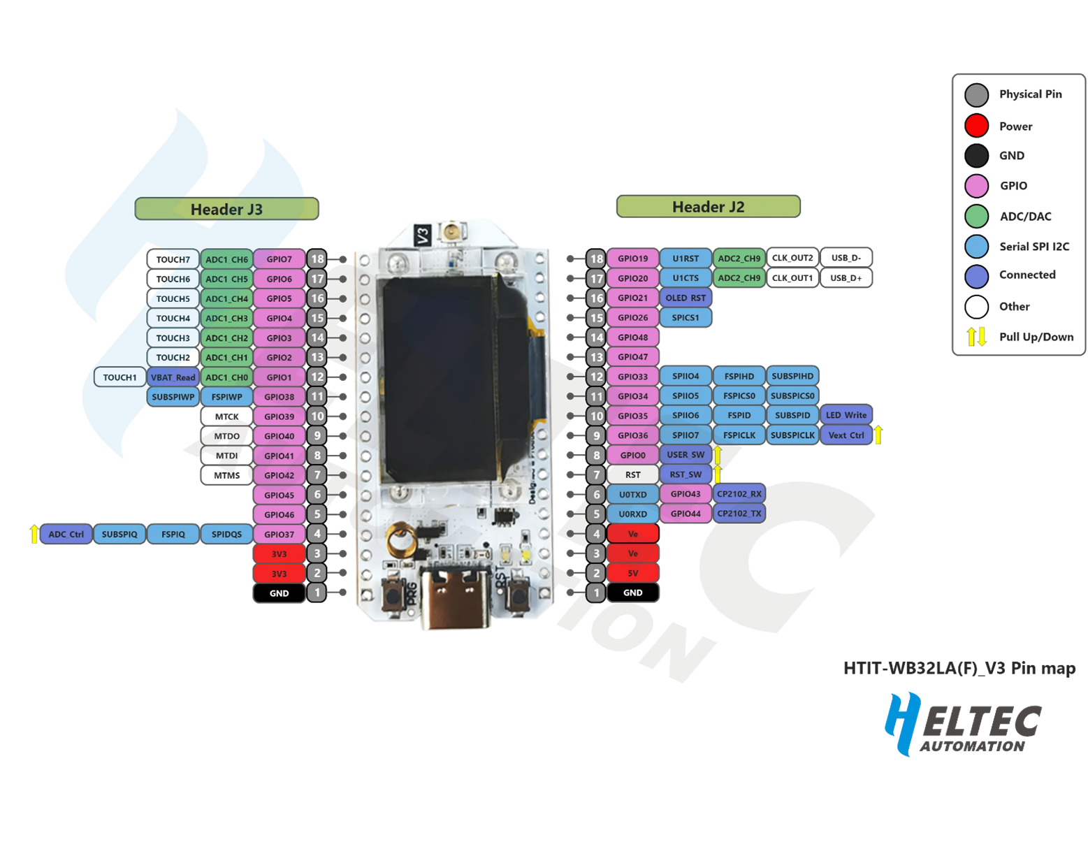
Pin Configuration and Descriptions

Pin Number Pin Name Description
1 3V3 3.3V Power Output
2 EN Enable Pin
3 GND Ground
4 23 GPIO 23
5 22 GPIO 22
6 21 GPIO 21
7 19 GPIO 19
8 18 GPIO 18
9 17 GPIO 17
10 16 GPIO 16
11 15 GPIO 15
12 14 GPIO 14
13 13 GPIO 13
14 12 GPIO 12
15 11 GPIO 11
16 10 GPIO 10
17 9 GPIO 9
18 8 GPIO 8
19 7 GPIO 7
20 6 GPIO 6
21 5 GPIO 5
22 4 GPIO 4
23 3 GPIO 3
24 2 GPIO 2
25 1 GPIO 1
26 0 GPIO 0

Usage Instructions

How to Use the Component in a Circuit

  1. Powering the Board:

    • Connect the board to a 5V power source via the USB port.
    • Ensure the 3.3V pin is used for any external components requiring 3.3V.
  2. Connecting to WiFi:

    • Use the built-in WiFi capabilities of the ESP32 to connect to a WiFi network.
    • Example code for connecting to WiFi:
      #include <WiFi.h>
      
      const char* ssid = "your_SSID";
      const char* password = "your_PASSWORD";
      
      void setup() {
        Serial.begin(115200);
        WiFi.begin(ssid, password);
      
        while (WiFi.status() != WL_CONNECTED) {
          delay(1000);
          Serial.println("Connecting to WiFi...");
        }
      
        Serial.println("Connected to WiFi");
      }
      
      void loop() {
        // Your code here
      }
      
  3. Using LoRa:

    • Utilize the LoRa library to send and receive data over long distances.
    • Example code for initializing LoRa:
      #include <SPI.h>
      #include <LoRa.h>
      
      void setup() {
        Serial.begin(115200);
        while (!Serial);
      
        Serial.println("LoRa Sender");
      
        if (!LoRa.begin(915E6)) { // Set frequency to 915 MHz
          Serial.println("Starting LoRa failed!");
          while (1);
        }
      }
      
      void loop() {
        Serial.print("Sending packet: ");
        Serial.println("Hello LoRa");
      
        // Send packet
        LoRa.beginPacket();
        LoRa.print("Hello LoRa");
        LoRa.endPacket();
      
        delay(1000);
      }
      

Important Considerations and Best Practices

  • Antenna Connection: Ensure that the appropriate antenna is connected to the board for both WiFi and LoRa to achieve optimal performance.
  • Power Supply: Use a stable power supply to avoid unexpected resets or malfunctions.
  • Pin Usage: Be mindful of the pin configuration to avoid conflicts, especially when using multiple peripherals.
  • Firmware Updates: Regularly check for firmware updates from Heltec to ensure the board operates with the latest features and bug fixes.

Troubleshooting and FAQs

Common Issues Users Might Face

  1. WiFi Connection Issues:

    • Solution: Verify the SSID and password. Ensure the WiFi network is within range and not experiencing interference.
  2. LoRa Communication Failures:

    • Solution: Check the frequency settings and ensure both sender and receiver are set to the same frequency. Verify antenna connections.
  3. Board Not Powering On:

    • Solution: Ensure the USB cable is functional and the power source provides sufficient current.
  4. GPIO Pin Conflicts:

    • Solution: Double-check the pin configuration in your code to avoid conflicts with other peripherals.

Solutions and Tips for Troubleshooting

  • Serial Monitor: Use the Serial Monitor for debugging and to get real-time feedback from the board.
  • Library Documentation: Refer to the official documentation for the WiFi and LoRa libraries for advanced configurations and troubleshooting tips.
  • Community Forums: Engage with the Heltec community forums for support and to share experiences with other users.

By following this documentation, users can effectively utilize the WiFi LoRa 32 (V3) development board for their IoT projects, leveraging its powerful combination of WiFi and LoRa technologies.