How to Use IR Break Beam Sensor: Examples, Pinouts, and Specs
Introduction
The IR Break Beam Sensor by Adafruit Industries is a reliable and easy-to-use sensor that consists of an infrared (IR) emitter and a photodetector. The sensor works by emitting an invisible IR beam from the emitter to the detector. When an object interrupts this beam, the sensor detects the break and outputs a signal. This makes it ideal for applications requiring object detection, counting, or motion sensing.
Explore Projects Built with IR Break Beam Sensor

Explore Projects Built with IR Break Beam Sensor
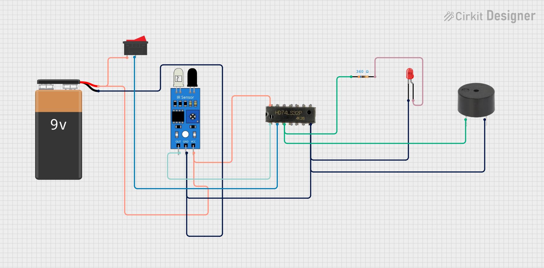
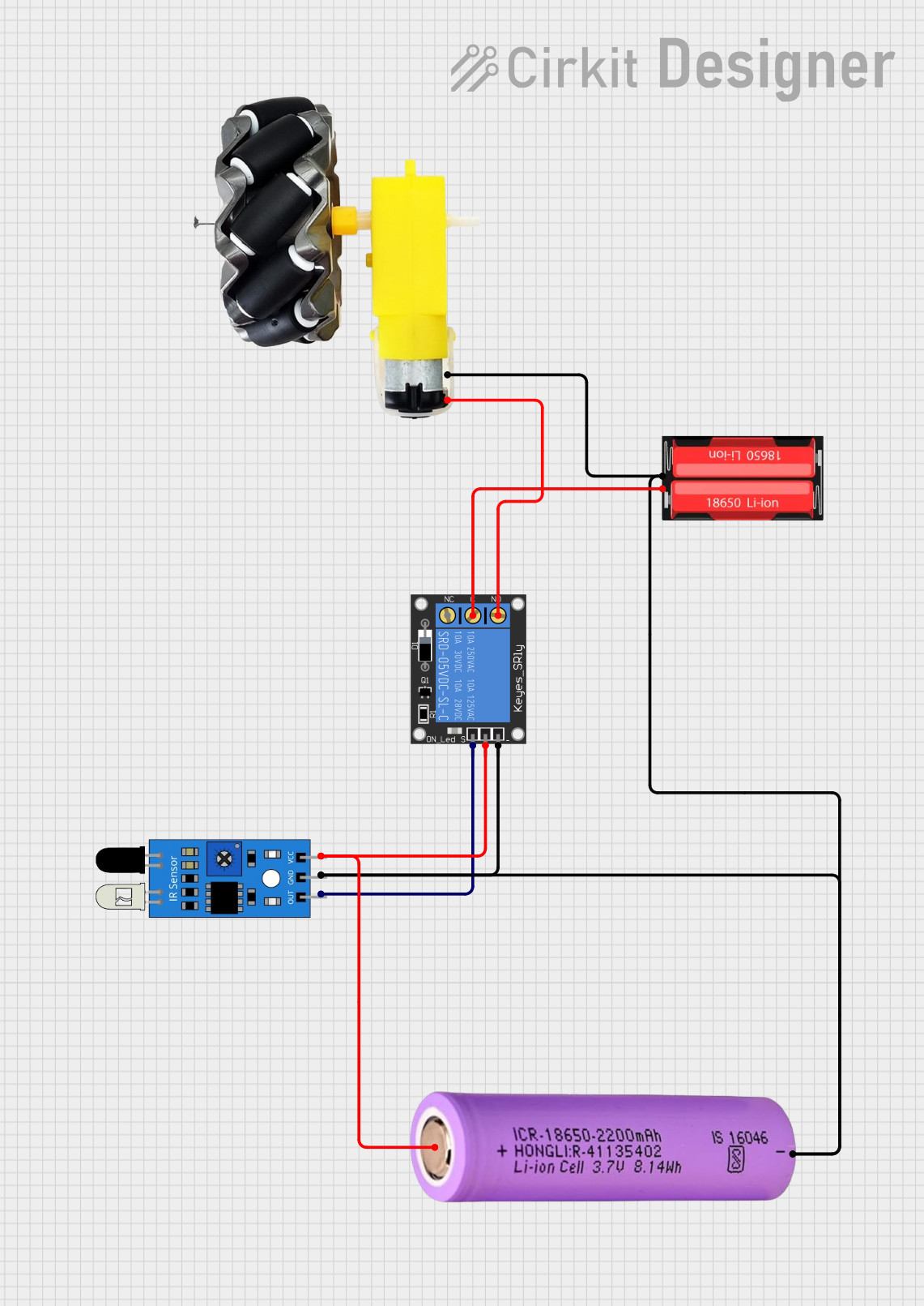
Common Applications
- Object detection in conveyor belts or assembly lines
- Entry/exit detection in doorways
- Counting objects or people
- Security systems and alarms
- Robotics and automation systems
Technical Specifications
Below are the key technical details for the IR Break Beam Sensor:
| Parameter | Value |
|---|---|
| Operating Voltage | 3.3V to 5V DC |
| Current Consumption | ~20mA (emitter) |
| Detection Range | Up to 50 cm (depending on alignment) |
| Output Signal | Digital (Active Low) |
| Beam Wavelength | 950 nm (infrared) |
| Response Time | < 1 ms |
| Operating Temperature | -25°C to 85°C |
Pin Configuration and Descriptions
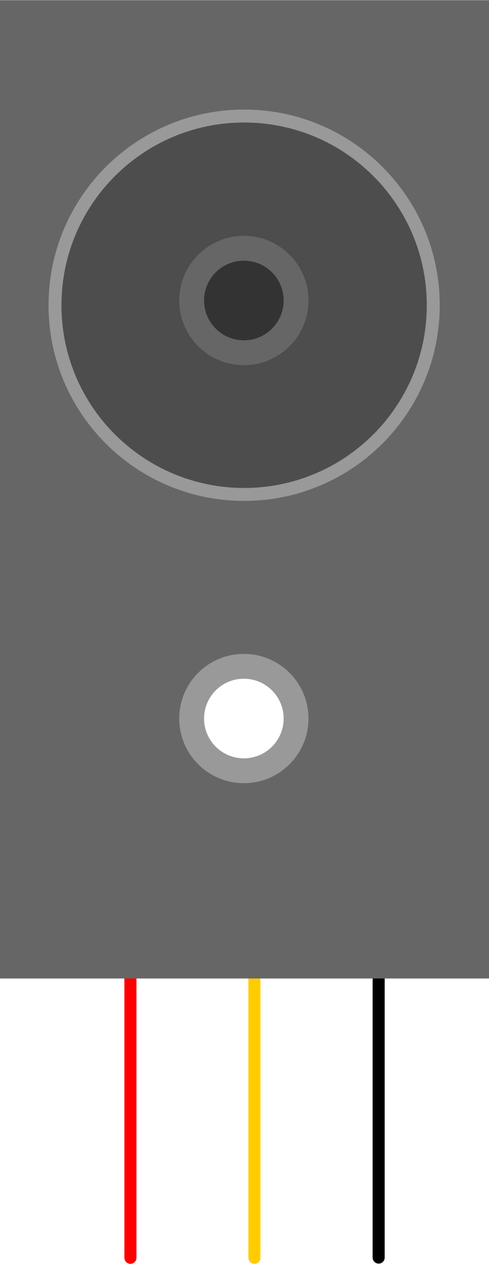
The IR Break Beam Sensor consists of two parts: the emitter and the receiver. Each part has two wires for connection.
Emitter
| Wire Color | Function |
|---|---|
| Red | Power (VCC) |
| Black | Ground (GND) |
Receiver
| Wire Color | Function |
|---|---|
| Red | Power (VCC) |
| Black | Ground (GND) |
| Yellow | Signal Output |
Usage Instructions
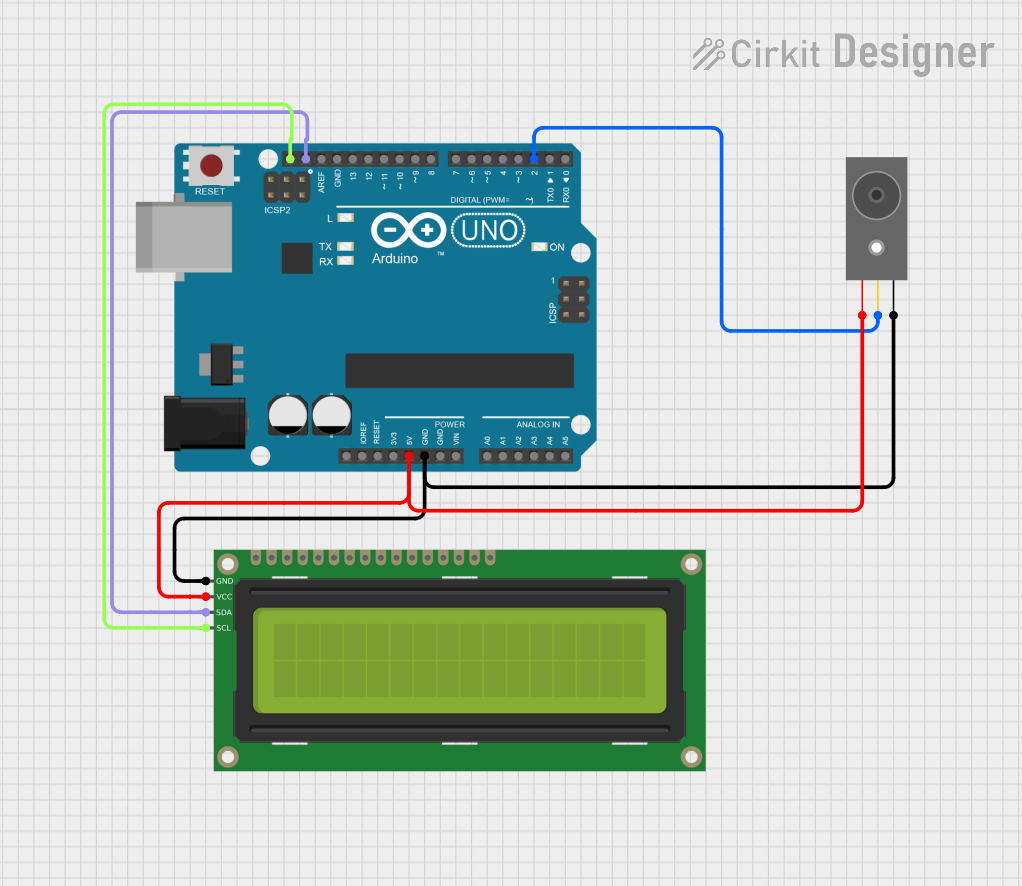
How to Use the IR Break Beam Sensor in a Circuit
Connect the Emitter:
- Connect the red wire of the emitter to a 3.3V or 5V power source.
- Connect the black wire of the emitter to ground (GND).
Connect the Receiver:
- Connect the red wire of the receiver to the same power source as the emitter.
- Connect the black wire of the receiver to ground (GND).
- Connect the yellow wire of the receiver to a digital input pin on your microcontroller or microprocessor.
Operation:
- When the IR beam is uninterrupted, the signal output (yellow wire) remains HIGH.
- When the IR beam is broken, the signal output goes LOW.
Important Considerations and Best Practices
- Alignment: Ensure the emitter and receiver are properly aligned for optimal performance. Misalignment can reduce the detection range or cause false readings.
- Power Supply: Use a stable power supply to avoid fluctuations in the IR beam.
- Interference: Avoid placing the sensor near strong light sources (e.g., sunlight) or reflective surfaces, as these can interfere with the IR beam.
- Mounting: Secure the emitter and receiver firmly to prevent movement, which could disrupt alignment.
Example Code for Arduino UNO
Below is an example of how to use the IR Break Beam Sensor with an Arduino UNO:
// IR Break Beam Sensor Example Code
// This code detects when the IR beam is broken and prints a message to the Serial Monitor.

#define SENSOR_PIN 2  // Connect the yellow wire of the receiver to digital pin 2

void setup() {
  pinMode(SENSOR_PIN, INPUT);  // Set the sensor pin as an input
  Serial.begin(9600);          // Initialize serial communication at 9600 baud
}

void loop() {
  int sensorState = digitalRead(SENSOR_PIN);  // Read the sensor's output

  if (sensorState == LOW) {
    // If the beam is broken, the sensor output goes LOW
    Serial.println("Beam broken! Object detected.");
  } else {
    // If the beam is uninterrupted, the sensor output remains HIGH
    Serial.println("Beam intact.");
  }

  delay(100);  // Small delay to avoid flooding the Serial Monitor
}
Troubleshooting and FAQs
Common Issues and Solutions
The sensor is not detecting objects:
- Solution: Check the alignment between the emitter and receiver. Ensure they are directly facing each other.
- Solution: Verify that the power connections are correct and the voltage is within the specified range.
False triggers or inconsistent readings:
- Solution: Ensure there are no reflective surfaces or strong light sources near the sensor.
- Solution: Use a stable power supply to avoid electrical noise.
No output signal from the receiver:
- Solution: Check the wiring connections, especially the yellow signal wire.
- Solution: Confirm that the emitter is powered and emitting an IR beam (use a camera to check for IR light).
FAQs
Q: Can the detection range be adjusted?
A: The detection range is fixed, but you can improve performance by ensuring proper alignment and avoiding obstructions.
Q: Can I use this sensor outdoors?
A: Yes, but avoid direct sunlight or extreme weather conditions, as these can interfere with the IR beam.
Q: What happens if the emitter and receiver are too far apart?
A: The sensor may fail to detect the IR beam, resulting in false readings. Keep the distance within the specified range (up to 50 cm).
Q: Can I use multiple IR Break Beam Sensors in the same project?
A: Yes, but ensure each sensor pair is properly aligned and does not interfere with others.