Cirkit Designer Logo
Cirkit Designer
Your all-in-one circuit design IDE
Home / 
Component Documentation

How to Use KY-024: Examples, Pinouts, and Specs

Image of KY-024
Cirkit Designer LogoDesign with KY-024 in Cirkit Designer

Introduction

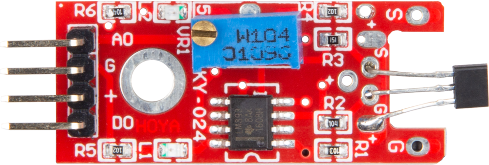
The KY-024 is a tilt sensor module designed to detect the angle of inclination. It operates using a ball switch mechanism, which closes the circuit when the module is tilted beyond a certain angle. This simple yet effective design makes the KY-024 ideal for applications requiring motion or tilt detection. Common use cases include robotics, gaming controllers, alarm systems, and other projects where orientation or movement needs to be monitored.

Explore Projects Built with KY-024

Use Cirkit Designer to design, explore, and prototype these projects online. Some projects support real-time simulation. Click "Open Project" to start designing instantly!
Wireless Joystick-Controlled Interface with Arduino Nano and NRF24L01
Image of Transmitter 11: A project utilizing KY-024 in a practical application
This circuit features an Arduino Nano interfaced with a KY-023 Dual Axis Joystick Module for analog input, and an NRF24L01 module for wireless communication. The joystick provides x and y-axis control signals to the Arduino's analog inputs and a switch signal to a digital input, while the NRF24L01 enables the Arduino to communicate with other devices wirelessly. The 2x 18650 batteries supply power to the Arduino, which in turn powers the joystick and the NRF24L01 module.
Cirkit Designer LogoOpen Project in Cirkit Designer
Arduino Nano Joystick-Controlled Wireless Communication System with NRF24L01
Image of Joystick/Transmitter: A project utilizing KY-024 in a practical application
This circuit features an Arduino Nano microcontroller interfaced with a KY-023 Dual Axis Joystick Module and an NRF24L01 wireless transceiver module. The joystick provides analog input to the Arduino, which can then transmit data wirelessly using the NRF24L01 module.
Cirkit Designer LogoOpen Project in Cirkit Designer
Arduino Nano Joystick-Controlled Bluetooth Module with Battery Power
Image of padelpro transmitter: A project utilizing KY-024 in a practical application
This circuit is a wireless joystick controller that uses an Arduino Nano to read analog signals from a KY-023 Dual Axis Joystick Module and transmits the data via an HC-05 Bluetooth Module. The system is powered by a 18650 Li-Ion battery with a rocker switch for power control.
Cirkit Designer LogoOpen Project in Cirkit Designer
Arduino Nano Controlled Joystick with NRF24L01 Wireless Communication
Image of drone remote: A project utilizing KY-024 in a practical application
This circuit features an Arduino Nano interfaced with two KY-023 Dual Axis Joystick Modules and an NRF24L01 wireless transceiver module. The joysticks provide X and Y axis inputs to the Arduino, which reads these analog signals and a button state, then transmits a message wirelessly via the NRF24L01. The circuit is likely used for remote control applications, with the Arduino processing joystick inputs and handling wireless communication to send control signals to a receiver.
Cirkit Designer LogoOpen Project in Cirkit Designer

Explore Projects Built with KY-024

Use Cirkit Designer to design, explore, and prototype these projects online. Some projects support real-time simulation. Click "Open Project" to start designing instantly!
Image of Transmitter 11: A project utilizing KY-024 in a practical application
Wireless Joystick-Controlled Interface with Arduino Nano and NRF24L01
This circuit features an Arduino Nano interfaced with a KY-023 Dual Axis Joystick Module for analog input, and an NRF24L01 module for wireless communication. The joystick provides x and y-axis control signals to the Arduino's analog inputs and a switch signal to a digital input, while the NRF24L01 enables the Arduino to communicate with other devices wirelessly. The 2x 18650 batteries supply power to the Arduino, which in turn powers the joystick and the NRF24L01 module.
Cirkit Designer LogoOpen Project in Cirkit Designer
Image of Joystick/Transmitter: A project utilizing KY-024 in a practical application
Arduino Nano Joystick-Controlled Wireless Communication System with NRF24L01
This circuit features an Arduino Nano microcontroller interfaced with a KY-023 Dual Axis Joystick Module and an NRF24L01 wireless transceiver module. The joystick provides analog input to the Arduino, which can then transmit data wirelessly using the NRF24L01 module.
Cirkit Designer LogoOpen Project in Cirkit Designer
Image of padelpro transmitter: A project utilizing KY-024 in a practical application
Arduino Nano Joystick-Controlled Bluetooth Module with Battery Power
This circuit is a wireless joystick controller that uses an Arduino Nano to read analog signals from a KY-023 Dual Axis Joystick Module and transmits the data via an HC-05 Bluetooth Module. The system is powered by a 18650 Li-Ion battery with a rocker switch for power control.
Cirkit Designer LogoOpen Project in Cirkit Designer
Image of drone remote: A project utilizing KY-024 in a practical application
Arduino Nano Controlled Joystick with NRF24L01 Wireless Communication
This circuit features an Arduino Nano interfaced with two KY-023 Dual Axis Joystick Modules and an NRF24L01 wireless transceiver module. The joysticks provide X and Y axis inputs to the Arduino, which reads these analog signals and a button state, then transmits a message wirelessly via the NRF24L01. The circuit is likely used for remote control applications, with the Arduino processing joystick inputs and handling wireless communication to send control signals to a receiver.
Cirkit Designer LogoOpen Project in Cirkit Designer

Technical Specifications

  • Operating Voltage: 3.3V to 5V
  • Output Type: Digital and Analog
  • Tilt Detection Angle: Approximately 15° to 45° (depending on orientation)
  • Dimensions: 32mm x 14mm x 8mm
  • Weight: ~3g
  • Operating Temperature: -40°C to +85°C

Pin Configuration and Descriptions

The KY-024 module has three pins for interfacing with external circuits. The table below describes each pin:

Pin Name Description
1 VCC Power supply pin. Connect to 3.3V or 5V.
2 GND Ground pin. Connect to the ground of the power supply.
3 DO Digital output pin. Outputs HIGH or LOW depending on the tilt state.
4 AO Analog output pin. Provides a variable voltage based on the tilt angle.

Usage Instructions

How to Use the KY-024 in a Circuit

  1. Power the Module: Connect the VCC pin to a 3.3V or 5V power source and the GND pin to the ground.
  2. Digital Output: Use the DO pin to detect tilt events. The pin outputs a HIGH signal when the module is tilted and LOW when it is not.
  3. Analog Output: Use the AO pin to measure the tilt angle. The output voltage varies with the angle of inclination.
  4. Adjust Sensitivity: The module includes a potentiometer to adjust the sensitivity of the tilt detection. Rotate the potentiometer clockwise or counterclockwise to fine-tune the detection threshold.

Important Considerations and Best Practices

  • Debouncing: The ball switch mechanism may cause signal bouncing. Use a capacitor or software debouncing techniques to stabilize the output.
  • Mounting Orientation: Ensure the module is mounted securely and in the correct orientation for accurate tilt detection.
  • Power Supply: Use a stable power source to avoid erratic behavior.
  • Environmental Factors: Avoid exposing the module to excessive vibration or shock, as this may affect its performance.

Example: Connecting KY-024 to an Arduino UNO

Below is an example of how to connect and use the KY-024 with an Arduino UNO to detect tilt events.

Circuit Connections

  • Connect the VCC pin of the KY-024 to the 5V pin on the Arduino.
  • Connect the GND pin of the KY-024 to the GND pin on the Arduino.
  • Connect the DO pin of the KY-024 to digital pin 2 on the Arduino.

Arduino Code

// KY-024 Tilt Sensor Example with Arduino UNO
// This code reads the digital output (DO) of the KY-024 and prints the tilt status.

const int tiltPin = 2; // KY-024 DO pin connected to digital pin 2
int tiltState = 0;     // Variable to store the tilt state

void setup() {
  pinMode(tiltPin, INPUT); // Set tiltPin as input
  Serial.begin(9600);      // Initialize serial communication at 9600 baud
}

void loop() {
  tiltState = digitalRead(tiltPin); // Read the tilt state from the KY-024

  if (tiltState == HIGH) {
    // If the tilt sensor is activated
    Serial.println("Tilt detected!");
  } else {
    // If the tilt sensor is not activated
    Serial.println("No tilt detected.");
  }

  delay(500); // Wait for 500ms before reading again
}

Troubleshooting and FAQs

Common Issues and Solutions

  1. No Output from the Module:

    • Ensure the power supply is connected correctly and within the operating voltage range.
    • Check the connections to the Arduino or other microcontroller.
    • Verify that the potentiometer is adjusted correctly for the desired sensitivity.
  2. Erratic or Unstable Output:

    • Use a capacitor across the power supply pins to filter noise.
    • Implement software debouncing in your code to handle signal bouncing.
  3. Analog Output Not Responding:

    • Ensure the AO pin is connected to an analog input pin on the microcontroller.
    • Verify that the tilt angle is within the detectable range of the module.

FAQs

Q: Can the KY-024 detect the exact angle of tilt?
A: The KY-024 provides an analog output (AO) that varies with the tilt angle, but it is not highly precise. For exact angle measurements, consider using a gyroscope or accelerometer module.

Q: How do I adjust the sensitivity of the tilt detection?
A: Use the onboard potentiometer to adjust the sensitivity. Rotate it clockwise or counterclockwise to increase or decrease the detection threshold.

Q: Can the KY-024 be used in battery-powered projects?
A: Yes, the KY-024 is suitable for battery-powered projects due to its low power consumption. Ensure the battery voltage matches the module's operating range.

Q: Is the KY-024 suitable for outdoor use?
A: The KY-024 is not weatherproof. If used outdoors, it should be enclosed in a protective casing to prevent damage from moisture or dust.