
How to Use MAX3421E: Examples, Pinouts, and Specs
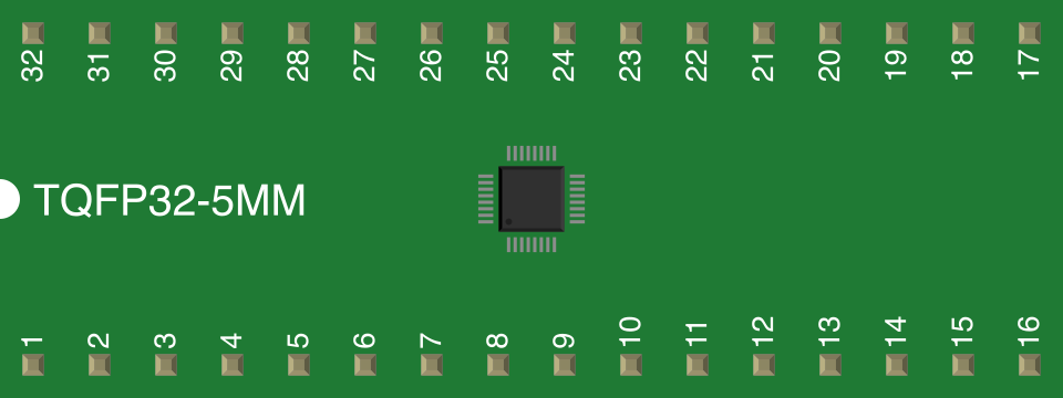
 Design with MAX3421E in Cirkit Designer
Introduction
The MAX3421E, manufactured by Analog Devices, is a USB peripheral controller designed to enable microcontrollers to interface seamlessly with USB devices. It supports full-speed USB 2.0 communication and features a straightforward SPI interface for communication with the host microcontroller. This makes it an ideal choice for applications requiring USB connectivity without the need for complex USB stack implementations.
Explore Projects Built with MAX3421E
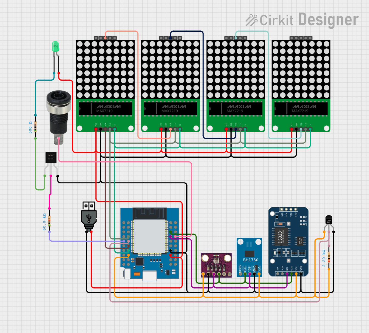 Open Project in Cirkit Designer
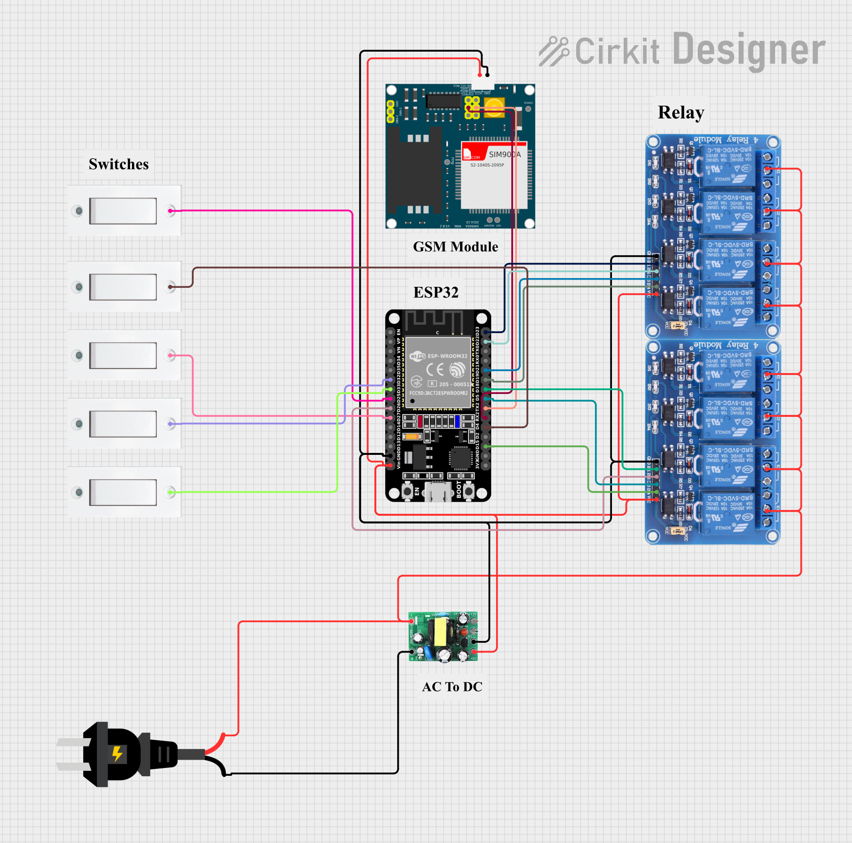 Open Project in Cirkit Designer
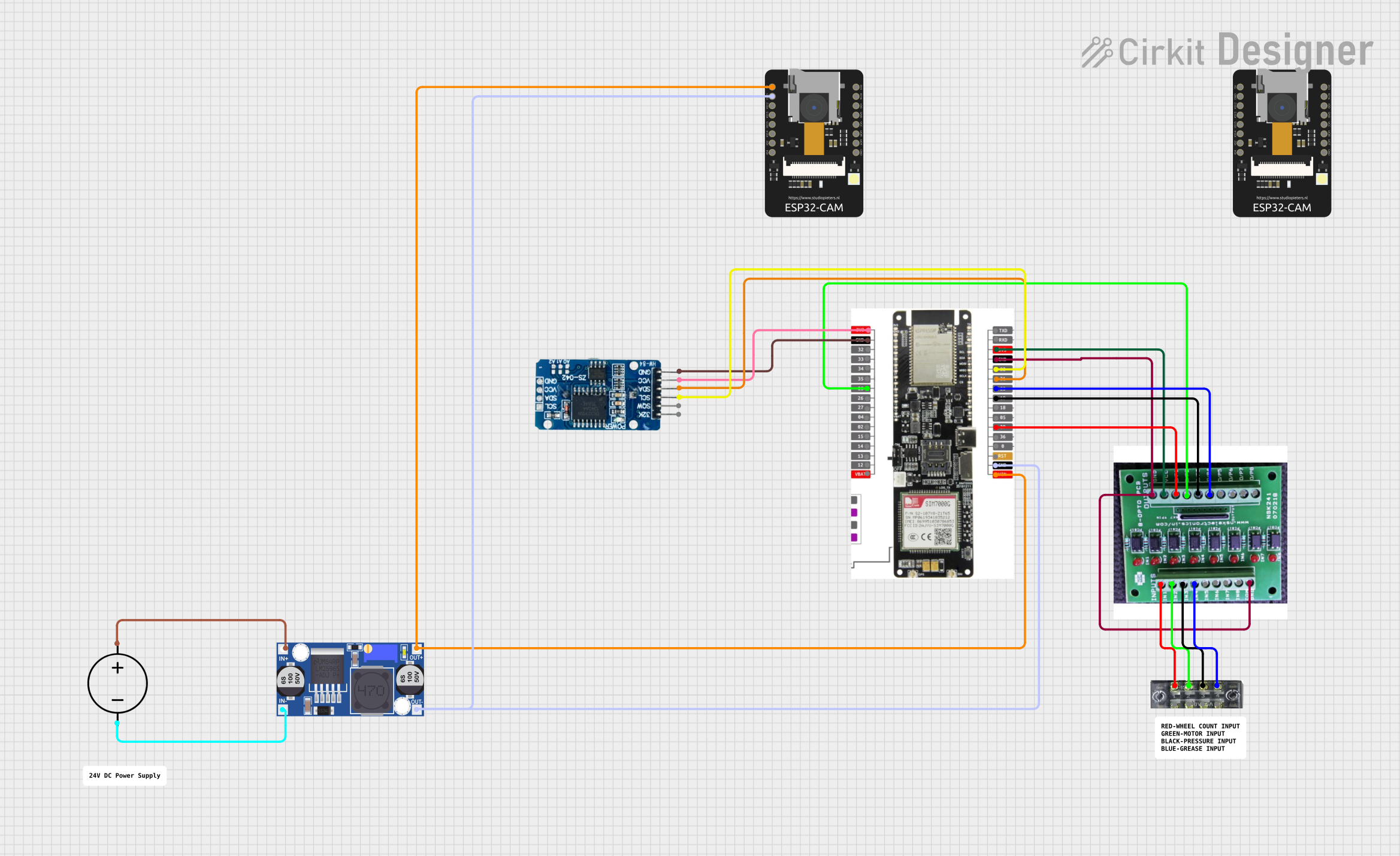 Open Project in Cirkit Designer
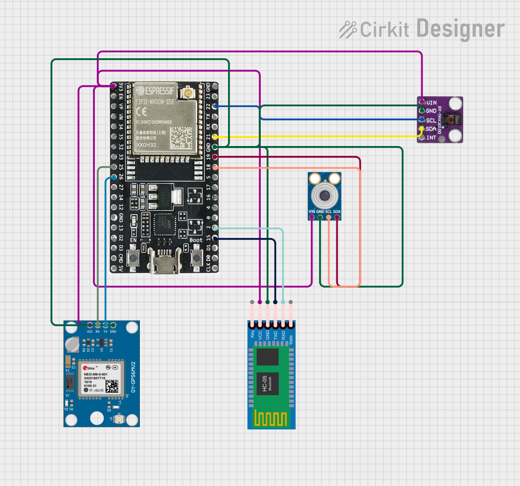 Open Project in Cirkit Designer
Explore Projects Built with MAX3421E
Open Project in Cirkit DesignerOpen Project in Cirkit DesignerOpen Project in Cirkit DesignerOpen Project in Cirkit DesignerCommon Applications and Use Cases
- USB host controllers for embedded systems
- USB device communication in microcontroller-based projects
- USB data logging and storage systems
- USB-to-serial converters
- Industrial and consumer electronics requiring USB connectivity
Technical Specifications
The MAX3421E is a versatile and robust component with the following key specifications:
| Parameter | Value |
|---|---|
| USB Standard | Full-Speed USB 2.0 (12 Mbps) |
| Communication Interface | SPI (Serial Peripheral Interface) |
| Operating Voltage Range | 3.0V to 3.6V |
| I/O Voltage Range | 1.8V to 3.6V |
| Operating Temperature Range | -40°C to +85°C |
| Package Type | 32-pin TQFP or 28-pin SSOP |
| Maximum SPI Clock Speed | 26 MHz |
| Power Consumption | Low-power operation |
Pin Configuration and Descriptions
The MAX3421E is available in a 32-pin TQFP or 28-pin SSOP package. Below is the pin configuration for the 32-pin TQFP package:
| Pin Number | Pin Name | Description |
|---|---|---|
| 1 | VCC | Power supply input (3.3V). |
| 2 | GND | Ground connection. |
| 3 | MOSI | SPI Master Out Slave In (data input from the microcontroller). |
| 4 | MISO | SPI Master In Slave Out (data output to the microcontroller). |
| 5 | SCK | SPI clock input. |
| 6 | SS | SPI slave select input (active low). |
| 7 | INT | Interrupt output (active low). Indicates USB events or SPI communication. |
| 8 | RESET | Active-low reset input. |
| 9-16 | D+ / D- | USB differential data lines. |
| 17-32 | NC / Other | Reserved or no-connect pins depending on the application. |
For the 28-pin SSOP package, refer to the manufacturer's datasheet for the exact pinout.
Usage Instructions
How to Use the MAX3421E in a Circuit
- Power Supply: Connect the VCC pin to a 3.3V power source and the GND pin to the ground.
- SPI Interface: Connect the SPI pins (MOSI, MISO, SCK, and SS) to the corresponding SPI pins on the microcontroller.
- USB Connection: Connect the D+ and D- pins to the USB device. Ensure proper termination resistors are used as per the USB specification.
- Interrupt Handling: Use the INT pin to detect USB events or communication status changes.
- Reset: Connect the RESET pin to the microcontroller or an external reset circuit for initialization.
Important Considerations and Best Practices
- Ensure the SPI clock speed does not exceed 26 MHz for reliable communication.
- Use decoupling capacitors (e.g., 0.1 µF) near the VCC pin to stabilize the power supply.
- Follow USB 2.0 design guidelines for PCB layout, especially for the D+ and D- differential pair.
- Use proper ESD protection for USB lines to prevent damage to the MAX3421E.
Example Code for Arduino UNO
The MAX3421E can be interfaced with an Arduino UNO using the SPI library. Below is an example code snippet to initialize the MAX3421E and check its status:
#include <SPI.h>

// Define SPI pins for Arduino UNO
#define SS_PIN 10  // Slave Select pin
#define INT_PIN 2  // Interrupt pin

void setup() {
  // Initialize serial communication for debugging
  Serial.begin(9600);

  // Configure SPI pins
  pinMode(SS_PIN, OUTPUT);
  pinMode(INT_PIN, INPUT);

  // Initialize SPI
  SPI.begin();
  SPI.setClockDivider(SPI_CLOCK_DIV8); // Set SPI clock speed
  SPI.setDataMode(SPI_MODE0);         // Set SPI mode
  SPI.setBitOrder(MSBFIRST);          // Set bit order

  // Reset MAX3421E
  digitalWrite(SS_PIN, LOW);
  SPI.transfer(0x01); // Example command to reset the MAX3421E
  digitalWrite(SS_PIN, HIGH);

  // Check if the MAX3421E is ready
  delay(100); // Wait for initialization
  Serial.println("MAX3421E initialized.");
}

void loop() {
  // Example: Check interrupt status
  if (digitalRead(INT_PIN) == LOW) {
    Serial.println("USB event detected.");
    // Add code to handle USB events
  }
}
Troubleshooting and FAQs
Common Issues and Solutions
No Communication with the MAX3421E
- Cause: Incorrect SPI connections or clock speed.
- Solution: Verify the SPI wiring and ensure the clock speed is within the specified range (≤26 MHz).
USB Device Not Recognized
- Cause: Improper USB connection or missing termination resistors.
- Solution: Check the D+ and D- connections and ensure proper termination resistors are used.
Interrupt Pin Not Triggering
- Cause: Incorrect interrupt pin configuration or firmware issue.
- Solution: Verify the INT pin connection and ensure the microcontroller firmware is correctly configured to handle interrupts.
Overheating
- Cause: Excessive current draw or incorrect power supply voltage.
- Solution: Ensure the power supply voltage is within the 3.0V to 3.6V range and check for short circuits.
FAQs
Q: Can the MAX3421E operate as a USB host?
A: Yes, the MAX3421E is designed to function as a USB host controller.Q: What is the maximum USB data rate supported?
A: The MAX3421E supports full-speed USB 2.0, which has a maximum data rate of 12 Mbps.Q: Is the MAX3421E compatible with 5V microcontrollers?
A: Yes, but level shifters may be required for SPI communication if the microcontroller operates at 5V logic levels.Q: Does the MAX3421E require an external crystal oscillator?
A: No, the MAX3421E has an internal clock source, but an external crystal can be used for precise timing if needed.
This concludes the documentation for the MAX3421E. For further details, refer to the official datasheet provided by Analog Devices.