Cirkit Designer Logo
Cirkit Designer
Your all-in-one circuit design IDE
Home / 
Component Documentation

How to Use đế ra chân và esp32 s3: Examples, Pinouts, and Specs

Image of đế ra chân và esp32 s3
Cirkit Designer LogoDesign with đế ra chân và esp32 s3 in Cirkit Designer

Introduction

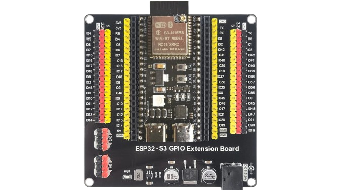
The "Đế Ra Chân" (commonly referred to as a breakout board) is a versatile accessory designed to simplify the connection and usage of microcontrollers like the ESP32-S3. The ESP32-S3 is a powerful, low-power microcontroller with integrated Wi-Fi and Bluetooth capabilities, making it ideal for IoT applications, smart devices, and wireless communication projects. When paired with a breakout board, the ESP32-S3 becomes easier to integrate into prototyping and development environments.

Explore Projects Built with đế ra chân và esp32 s3

Use Cirkit Designer to design, explore, and prototype these projects online. Some projects support real-time simulation. Click "Open Project" to start designing instantly!
ESP32-S3 Based Vibration Detection System with TFT Display and Power Backup
Image of IOT Thesis: A project utilizing đế ra chân và esp32 s3 in a practical application
This circuit features an ESP32-S3 microcontroller connected to various peripherals including an ADXL355 accelerometer, an SW-420 vibration sensor, a buzzer module, and an ILI9341 TFT display. The ESP32-S3 manages sensor inputs and provides output to the display and buzzer. Power management is handled by a 12V to 5V step-down converter, and a UPS ensures uninterrupted power supply, with a rocker switch to control the power flow.
Cirkit Designer LogoOpen Project in Cirkit Designer
ESP32-S3 Based Environmental Monitoring and Control System with Data Logging
Image of ESP32: A project utilizing đế ra chân và esp32 s3 in a practical application
This circuit features an ESP32-S3 microcontroller interfaced with various sensors and modules, including a DHT22 temperature and humidity sensor, an HC-SR04 ultrasonic sensor, an SGP41 VOC and NOx sensor, and an Adafruit INA260 current and power sensor. The ESP32-S3 also controls a DC motor via a relay and communicates with an SD card and an OLED display. An Arduino UNO is used to read inputs from a rotary encoder, and a step-down buck converter is used to regulate voltage from a 12V battery to power the components.
Cirkit Designer LogoOpen Project in Cirkit Designer
ESP32-S3 GPS and Wind Speed Logger with Dual OLED Displays and CAN Bus
Image of esp32-s3-ellipse: A project utilizing đế ra chân và esp32 s3 in a practical application
This circuit features an ESP32-S3 microcontroller interfaced with an SD card module, two OLED displays, a GPS module, and a CAN bus module. The ESP32-S3 records GPS data to the SD card, displays speed on one OLED, and shows wind speed from the CAN bus on the other OLED, providing a comprehensive data logging and display system.
Cirkit Designer LogoOpen Project in Cirkit Designer
ESP32-S3 Based Smart IoT Distance Sensor with Ethernet Connectivity
Image of ttt: A project utilizing đế ra chân và esp32 s3 in a practical application
This circuit features an ESP32-S3 microcontroller interfaced with a KY-019 Relay module, a VL53L1X time-of-flight sensor, and a W5500 Ethernet module. The ESP32-S3 controls the relay and communicates with the VL53L1X sensor via I2C, as well as with the network through the Ethernet module. An AC source is converted to DC for powering the components, and a micro USB connection is used to trigger the relay.
Cirkit Designer LogoOpen Project in Cirkit Designer

Explore Projects Built with đế ra chân và esp32 s3

Use Cirkit Designer to design, explore, and prototype these projects online. Some projects support real-time simulation. Click "Open Project" to start designing instantly!
Image of IOT Thesis: A project utilizing đế ra chân và esp32 s3 in a practical application
ESP32-S3 Based Vibration Detection System with TFT Display and Power Backup
This circuit features an ESP32-S3 microcontroller connected to various peripherals including an ADXL355 accelerometer, an SW-420 vibration sensor, a buzzer module, and an ILI9341 TFT display. The ESP32-S3 manages sensor inputs and provides output to the display and buzzer. Power management is handled by a 12V to 5V step-down converter, and a UPS ensures uninterrupted power supply, with a rocker switch to control the power flow.
Cirkit Designer LogoOpen Project in Cirkit Designer
Image of ESP32: A project utilizing đế ra chân và esp32 s3 in a practical application
ESP32-S3 Based Environmental Monitoring and Control System with Data Logging
This circuit features an ESP32-S3 microcontroller interfaced with various sensors and modules, including a DHT22 temperature and humidity sensor, an HC-SR04 ultrasonic sensor, an SGP41 VOC and NOx sensor, and an Adafruit INA260 current and power sensor. The ESP32-S3 also controls a DC motor via a relay and communicates with an SD card and an OLED display. An Arduino UNO is used to read inputs from a rotary encoder, and a step-down buck converter is used to regulate voltage from a 12V battery to power the components.
Cirkit Designer LogoOpen Project in Cirkit Designer
Image of esp32-s3-ellipse: A project utilizing đế ra chân và esp32 s3 in a practical application
ESP32-S3 GPS and Wind Speed Logger with Dual OLED Displays and CAN Bus
This circuit features an ESP32-S3 microcontroller interfaced with an SD card module, two OLED displays, a GPS module, and a CAN bus module. The ESP32-S3 records GPS data to the SD card, displays speed on one OLED, and shows wind speed from the CAN bus on the other OLED, providing a comprehensive data logging and display system.
Cirkit Designer LogoOpen Project in Cirkit Designer
Image of ttt: A project utilizing đế ra chân và esp32 s3 in a practical application
ESP32-S3 Based Smart IoT Distance Sensor with Ethernet Connectivity
This circuit features an ESP32-S3 microcontroller interfaced with a KY-019 Relay module, a VL53L1X time-of-flight sensor, and a W5500 Ethernet module. The ESP32-S3 controls the relay and communicates with the VL53L1X sensor via I2C, as well as with the network through the Ethernet module. An AC source is converted to DC for powering the components, and a micro USB connection is used to trigger the relay.
Cirkit Designer LogoOpen Project in Cirkit Designer

Common Applications and Use Cases

  • IoT devices and smart home automation
  • Wireless communication systems (Wi-Fi and Bluetooth)
  • Sensor data acquisition and processing
  • Robotics and motor control
  • Edge computing and AI/ML applications

Technical Specifications

ESP32-S3 Specifications

Parameter Value
Microcontroller ESP32-S3 (Xtensa® 32-bit LX7 dual-core)
Clock Speed Up to 240 MHz
Flash Memory 4 MB (varies by model)
RAM 512 KB SRAM + 8 MB PSRAM (optional)
Wi-Fi 802.11 b/g/n (2.4 GHz)
Bluetooth Bluetooth 5.0 LE
GPIO Pins Up to 45 GPIO pins
Operating Voltage 3.3V
Power Supply 5V via USB or 3.3V via VIN

Đế Ra Chân (Breakout Board) Pin Configuration

The breakout board provides easy access to the ESP32-S3's pins. Below is the pinout description:

Pin Name Description
VIN Power input (5V)
GND Ground
3V3 3.3V power output
GPIO0 General-purpose I/O, boot mode selection
GPIO1-45 General-purpose I/O pins
TXD UART Transmit
RXD UART Receive
EN Enable pin (reset ESP32-S3)
IOREF Reference voltage for I/O
SDA I2C Data
SCL I2C Clock
SPI Pins MOSI, MISO, SCK, CS

Usage Instructions

How to Use the Component in a Circuit

  1. Powering the ESP32-S3:

    • Connect the VIN pin to a 5V power source or use the USB port for power.
    • Ensure the GND pin is connected to the ground of your circuit.
  2. Connecting Peripherals:

    • Use the GPIO pins to connect sensors, actuators, or other peripherals.
    • For I2C devices, connect SDA and SCL to the corresponding pins on the breakout board.
  3. Programming the ESP32-S3:

    • Use a USB cable to connect the breakout board to your computer.
    • Install the ESP32 board package in the Arduino IDE or use the ESP-IDF framework.
  4. Uploading Code:

    • Select the correct board (e.g., "ESP32-S3 Dev Module") in the Arduino IDE.
    • Press the "Upload" button to flash your code to the ESP32-S3.

Important Considerations and Best Practices

  • Voltage Levels: Ensure all connected peripherals operate at 3.3V logic levels to avoid damaging the ESP32-S3.
  • Boot Mode: To enter boot mode for flashing firmware, hold the BOOT button while pressing the EN (reset) button.
  • Power Supply: Use a stable power source to avoid unexpected resets or performance issues.
  • Pin Multiplexing: Many GPIO pins have multiple functions (e.g., UART, I2C, SPI). Check the datasheet to avoid conflicts.

Example Code for Arduino UNO Integration

Below is an example of using the ESP32-S3 to read data from a DHT11 temperature and humidity sensor:

#include <Adafruit_Sensor.h>
#include <DHT.h>
#include <DHT_U.h>

// Define the DHT sensor type and GPIO pin
#define DHTPIN 4  // Connect DHT data pin to GPIO4
#define DHTTYPE DHT11  // DHT11 sensor type

DHT dht(DHTPIN, DHTTYPE);

void setup() {
  Serial.begin(115200);  // Initialize serial communication
  dht.begin();  // Initialize the DHT sensor
  Serial.println("DHT11 Sensor Example with ESP32-S3");
}

void loop() {
  // Read temperature and humidity values
  float humidity = dht.readHumidity();
  float temperature = dht.readTemperature();

  // Check if the readings are valid
  if (isnan(humidity) || isnan(temperature)) {
    Serial.println("Failed to read from DHT sensor!");
    return;
  }

  // Print the readings to the Serial Monitor
  Serial.print("Humidity: ");
  Serial.print(humidity);
  Serial.print("%  Temperature: ");
  Serial.print(temperature);
  Serial.println("°C");

  delay(2000);  // Wait 2 seconds before the next reading
}

Troubleshooting and FAQs

Common Issues

  1. ESP32-S3 Not Detected by Computer:

    • Ensure the USB cable is functional and supports data transfer.
    • Install the correct USB-to-serial driver for your operating system.
  2. Code Upload Fails:

    • Check that the correct board and COM port are selected in the Arduino IDE.
    • Hold the BOOT button while pressing the EN button to enter boot mode.
  3. Peripherals Not Working:

    • Verify the wiring and connections.
    • Ensure the peripherals are compatible with 3.3V logic levels.

Solutions and Tips for Troubleshooting

  • Debugging with Serial Monitor: Use Serial.print() statements to debug your code and monitor the ESP32-S3's behavior.
  • Check Power Supply: Use a multimeter to ensure the ESP32-S3 is receiving the correct voltage.
  • Update Firmware: If issues persist, try updating the ESP32-S3's firmware using the ESP-IDF or Arduino IDE.

By following this documentation, you can effectively use the Đế Ra Chân and ESP32-S3 for a wide range of applications.