How to Use pimoroni pico lipo: Examples, Pinouts, and Specs
Introduction
The Pimoroni Pico Lipo (Manufacturer Part ID: PIM560) is a power management board designed specifically for the Raspberry Pi Pico. It enables the Pico to be powered by a lithium polymer (LiPo) battery, making it an ideal choice for portable and battery-powered projects. The board features an integrated LiPo battery charger, allowing users to charge the battery via USB while still powering the Pico. Its compact design ensures it fits seamlessly into projects where space is a constraint.
Explore Projects Built with pimoroni pico lipo
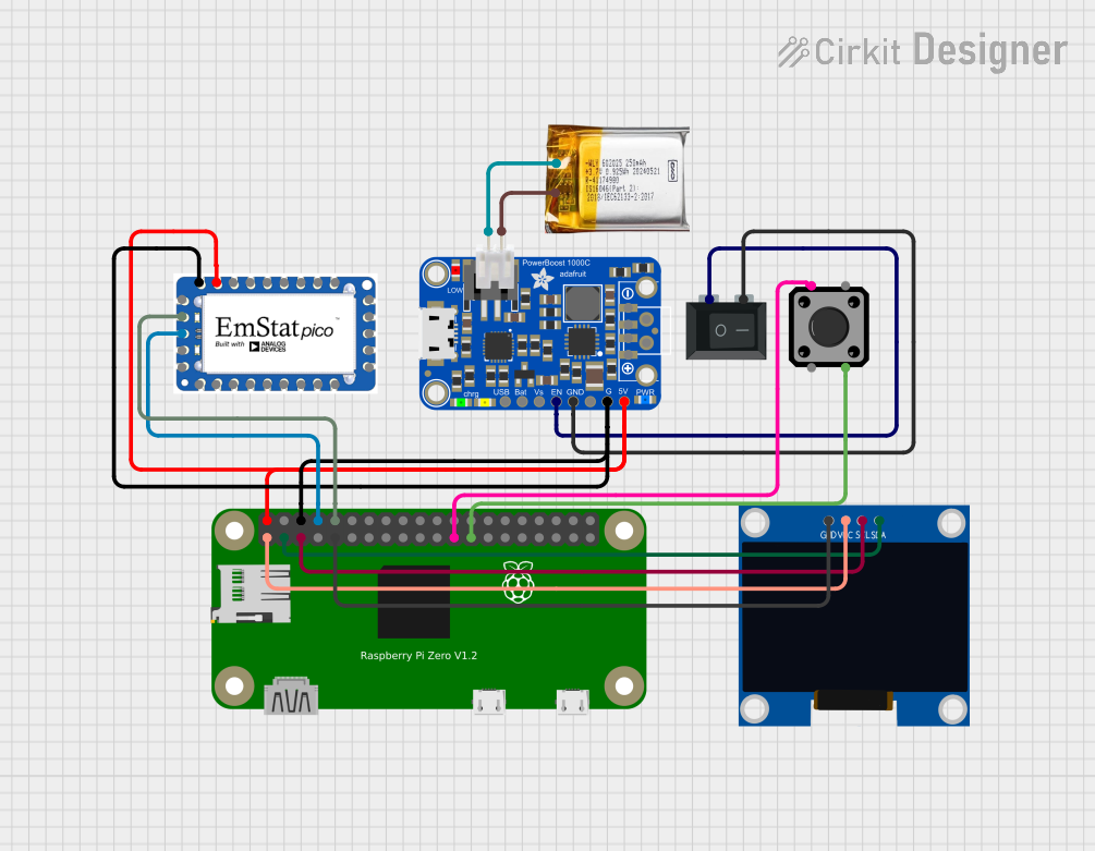
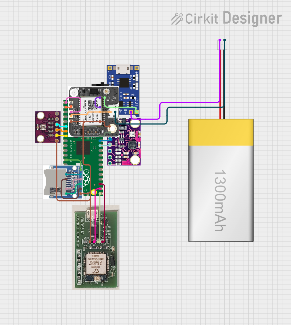


Explore Projects Built with pimoroni pico lipo
Common Applications and Use Cases
- Portable IoT devices
- Wearable electronics
- Robotics and automation
- Battery-powered data loggers
- Educational and prototyping projects
Technical Specifications
The Pimoroni Pico Lipo is designed to provide reliable power management for the Raspberry Pi Pico. Below are its key technical details:
Key Specifications
| Parameter | Value |
|---|---|
| Input Voltage | 5V (via USB-C) |
| Battery Compatibility | Single-cell LiPo/Li-ion (3.7V) |
| Charging Current | 450mA |
| Output Voltage | 5V (regulated) |
| Output Current | Up to 1.5A |
| Dimensions | 51mm x 21mm x 8mm |
| Connector Type | USB-C for charging |
| Battery Connector | JST-PH 2.0 |
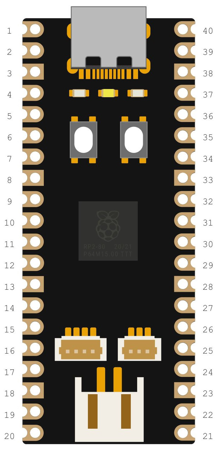
Pin Configuration and Descriptions
The Pimoroni Pico Lipo connects directly to the Raspberry Pi Pico via its pin headers. Below is the pin configuration:
| Pin Name | Description |
|---|---|
| VSYS | Supplies power to the Pico (regulated 5V from USB or battery). |
| GND | Ground connection. |
| 3V3_EN | Enables or disables the 3.3V regulator on the Pico. |
| VBAT | Direct connection to the LiPo battery voltage (unregulated). |
| CHG | Indicates the charging status (active low when charging). |
| PWR | Indicates power status (high when powered via USB or battery). |
Usage Instructions
The Pimoroni Pico Lipo is straightforward to use and integrates seamlessly with the Raspberry Pi Pico. Follow the steps below to get started:
Connecting the Battery
- Connect a single-cell LiPo or Li-ion battery (3.7V nominal) to the JST-PH 2.0 connector on the Pimoroni Pico Lipo.
- Ensure the battery is securely connected to avoid intermittent power issues.
Powering the Pico
- The Pimoroni Pico Lipo automatically switches between USB power and battery power. When USB is connected, it powers the Pico and charges the battery simultaneously.
- The regulated 5V output is supplied to the Pico via the VSYS pin.
Charging the Battery
- Connect a USB-C cable to the Pimoroni Pico Lipo and a power source (e.g., a computer or USB wall adapter).
- The CHG pin will go low (active) while the battery is charging. Once fully charged, the CHG pin will go high.
Important Considerations
- Use only single-cell LiPo or Li-ion batteries with a nominal voltage of 3.7V.
- Avoid shorting the battery terminals or connecting incompatible batteries.
- Ensure proper ventilation if the board is used in an enclosed space, as charging may generate heat.
Example Code for Arduino (Using Raspberry Pi Pico with Arduino IDE)
The following example demonstrates how to monitor the battery voltage using the VBAT pin:
// Example code to read battery voltage from VBAT pin on Pimoroni Pico Lipo
// Ensure the VBAT pin is connected to an ADC pin on the Pico (e.g., ADC0).

const int vbatPin = A0; // Replace A0 with the ADC pin connected to VBAT
const float voltageDivider = 2.0; // Voltage divider ratio on VBAT pin
const float adcReference = 3.3; // ADC reference voltage (3.3V)
const int adcResolution = 1024; // ADC resolution (10-bit)

void setup() {
  Serial.begin(9600); // Initialize serial communication
  while (!Serial);    // Wait for the serial monitor to open
  Serial.println("Pimoroni Pico Lipo Battery Voltage Monitor");
}

void loop() {
  int adcValue = analogRead(vbatPin); // Read ADC value from VBAT pin
  float batteryVoltage = (adcValue * adcReference / adcResolution) * voltageDivider;

  // Print the battery voltage to the serial monitor
  Serial.print("Battery Voltage: ");
  Serial.print(batteryVoltage);
  Serial.println(" V");

  delay(1000); // Wait for 1 second before the next reading
}
Best Practices
- Regularly monitor the battery voltage to prevent over-discharge, which can damage the battery.
- Disconnect the battery if the board will not be used for an extended period to prevent deep discharge.
- Use a high-quality USB-C cable and power source for reliable charging.
Troubleshooting and FAQs
Common Issues and Solutions
The Pico does not power on when connected to the battery.
- Ensure the battery is properly connected to the JST-PH 2.0 connector.
- Check the battery voltage; it should be above 3.0V for proper operation.
The battery does not charge when connected to USB.
- Verify that the USB-C cable and power source are functioning correctly.
- Check the CHG pin status to confirm if charging is active.
- Ensure the battery is compatible (single-cell LiPo or Li-ion).
The board overheats during operation.
- Ensure the board is not enclosed in a poorly ventilated space.
- Check for any short circuits or excessive current draw from the connected devices.
The CHG or PWR indicator LEDs are not functioning.
- Inspect the board for physical damage or loose connections.
- Verify the power source and battery connections.
FAQs
Q: Can I use a different type of battery with the Pimoroni Pico Lipo?
A: No, the board is designed specifically for single-cell LiPo or Li-ion batteries with a nominal voltage of 3.7V.
Q: What happens if I connect both USB and battery power?
A: The Pimoroni Pico Lipo automatically switches to USB power and charges the battery simultaneously.
Q: Can I use the Pimoroni Pico Lipo with other microcontrollers?
A: While it is designed for the Raspberry Pi Pico, it can be used with other microcontrollers that accept a 5V input via VSYS or similar pins.
Q: How do I know when the battery is fully charged?
A: The CHG pin will go high (inactive) when the battery is fully charged.
By following this documentation, you can effectively integrate the Pimoroni Pico Lipo into your projects and ensure reliable performance.