
How to Use Hub Motor: Examples, Pinouts, and Specs
 Design with Hub Motor in Cirkit Designer
Introduction
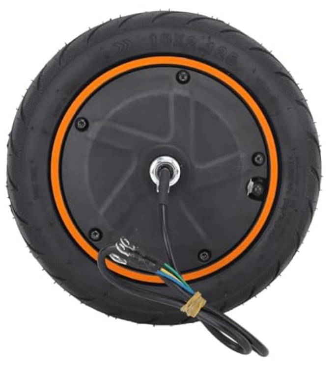
A hub motor is an electric motor integrated directly into the wheel hub of a vehicle, eliminating the need for external transmission systems. This design allows the motor to provide direct drive to the wheel, resulting in a compact and efficient solution for electric propulsion. Hub motors are widely used in electric bicycles, scooters, and other electric vehicles due to their simplicity, reliability, and ease of installation.
Explore Projects Built with Hub Motor
 Open Project in Cirkit Designer
 Open Project in Cirkit Designer
 Open Project in Cirkit Designer
 Open Project in Cirkit Designer
Explore Projects Built with Hub Motor
Open Project in Cirkit DesignerOpen Project in Cirkit DesignerOpen Project in Cirkit DesignerOpen Project in Cirkit DesignerCommon Applications and Use Cases
- Electric bicycles (e-bikes)
- Electric scooters
- Electric motorcycles
- Autonomous robots and vehicles
- Lightweight electric cars
- Industrial machinery requiring compact motorized wheels
Technical Specifications
Below are the general technical specifications for a typical hub motor. Note that specific values may vary depending on the manufacturer and model.
General Specifications
| Parameter | Value |
|---|---|
| Motor Type | Brushless DC (BLDC) or Brushed |
| Voltage Range | 24V, 36V, 48V, or higher |
| Power Output | 250W to 2000W (or more) |
| Torque | 10 Nm to 100 Nm |
| Speed | 200 RPM to 1000 RPM |
| Efficiency | Up to 90% |
| Weight | 2 kg to 10 kg (depending on size) |
Pin Configuration and Descriptions
For a brushless hub motor, the wiring typically includes the following connections:
| Pin/Wire Color | Function | Description |
|---|---|---|
| Yellow | Phase A | One of the three motor phase wires |
| Green | Phase B | One of the three motor phase wires |
| Blue | Phase C | One of the three motor phase wires |
| Red | Hall Sensor Power (+5V) | Supplies power to the Hall sensors |
| Black | Hall Sensor Ground | Ground connection for the Hall sensors |
| Yellow (thin) | Hall Sensor A | Outputs position feedback from Hall sensor A |
| Green (thin) | Hall Sensor B | Outputs position feedback from Hall sensor B |
| Blue (thin) | Hall Sensor C | Outputs position feedback from Hall sensor C |
Note: Some hub motors may include additional wires for features like temperature sensors or electronic braking.
Usage Instructions
How to Use the Hub Motor in a Circuit
- Power Supply: Ensure the motor is connected to a power supply that matches its voltage and current requirements. For example, a 36V hub motor should be powered by a 36V battery pack.
- Motor Controller: Use a compatible motor controller to drive the hub motor. The controller manages the power delivery and interprets signals from the Hall sensors for smooth operation.
- Wiring: Connect the motor phase wires (Yellow, Green, Blue) to the corresponding outputs on the motor controller. Similarly, connect the Hall sensor wires to the controller's Hall sensor inputs.
- Throttle/Control Input: Attach a throttle or control input (e.g., potentiometer or Arduino) to the motor controller to regulate speed and direction.
- Testing: Before full operation, test the motor at low speeds to ensure proper wiring and functionality.
Important Considerations and Best Practices
- Voltage Compatibility: Always match the motor's voltage rating with the power supply and controller.
- Heat Management: Avoid prolonged operation at maximum power to prevent overheating.
- Waterproofing: If used in outdoor applications, ensure the motor is adequately sealed against water and dust.
- Controller Settings: Configure the motor controller for the correct motor type (e.g., BLDC or brushed) and parameters.
- Safety: Use appropriate fuses and circuit breakers to protect the motor and controller from overcurrent.
Example: Controlling a Hub Motor with Arduino UNO
Below is an example of how to control a hub motor using an Arduino UNO and a motor controller.
// Example: Controlling a hub motor with Arduino UNO
// This code uses PWM to control motor speed via a motor controller.

// Define the PWM pin for motor speed control
const int motorPWM = 9; // Connect to the motor controller's PWM input

// Define the direction control pin
const int motorDir = 8; // Connect to the motor controller's direction input

void setup() {
  // Set the motor control pins as outputs
  pinMode(motorPWM, OUTPUT);
  pinMode(motorDir, OUTPUT);

  // Initialize motor direction to forward
  digitalWrite(motorDir, HIGH);
}

void loop() {
  // Gradually increase motor speed
  for (int speed = 0; speed <= 255; speed++) {
    analogWrite(motorPWM, speed); // Set motor speed (0-255)
    delay(20); // Wait for 20ms
  }

  // Gradually decrease motor speed
  for (int speed = 255; speed >= 0; speed--) {
    analogWrite(motorPWM, speed); // Set motor speed (0-255)
    delay(20); // Wait for 20ms
  }

  // Reverse motor direction
  digitalWrite(motorDir, LOW);
  delay(1000); // Wait for 1 second before repeating
}
Note: Ensure the motor controller supports PWM input and is compatible with the Arduino's 5V logic level.
Troubleshooting and FAQs
Common Issues and Solutions
Motor Does Not Spin
- Cause: Incorrect wiring or loose connections.
- Solution: Double-check all connections, especially the phase wires and Hall sensor wires.
Motor Spins in the Wrong Direction
- Cause: Phase wires are connected in the wrong order.
- Solution: Swap any two of the three phase wires to reverse the motor's direction.
Motor Overheats
- Cause: Prolonged operation at high power or insufficient cooling.
- Solution: Reduce the load on the motor or add external cooling (e.g., a fan).
Jerky or Noisy Operation
- Cause: Faulty Hall sensors or incorrect controller settings.
- Solution: Test the Hall sensors and ensure the controller is configured for the correct motor type.
Controller Does Not Respond
- Cause: Incorrect throttle input or damaged controller.
- Solution: Verify the throttle wiring and test the controller with a known working input.
FAQs
Can I use a hub motor without a controller? No, a motor controller is essential for regulating power delivery and interpreting Hall sensor signals.
What is the difference between a brushed and brushless hub motor? A brushed motor uses mechanical brushes for commutation, while a brushless motor uses electronic commutation, offering higher efficiency and durability.
Can I use a hub motor for regenerative braking? Yes, many hub motors support regenerative braking when paired with a compatible controller.
How do I calculate the required battery capacity for my hub motor? Multiply the motor's power rating (in watts) by the desired runtime (in hours) and divide by the battery voltage to get the capacity in ampere-hours (Ah).
Is it possible to use a hub motor in water? Only if the motor is specifically designed to be waterproof. Otherwise, exposure to water can damage the motor and its components.