Cirkit Designer Logo
Cirkit Designer
Your all-in-one circuit design IDE
Home / 
Component Documentation

How to Use ME60N03 4-Channel Mosfet 3: Examples, Pinouts, and Specs

Image of ME60N03 4-Channel Mosfet 3
Cirkit Designer LogoDesign with ME60N03 4-Channel Mosfet 3 in Cirkit Designer

Introduction

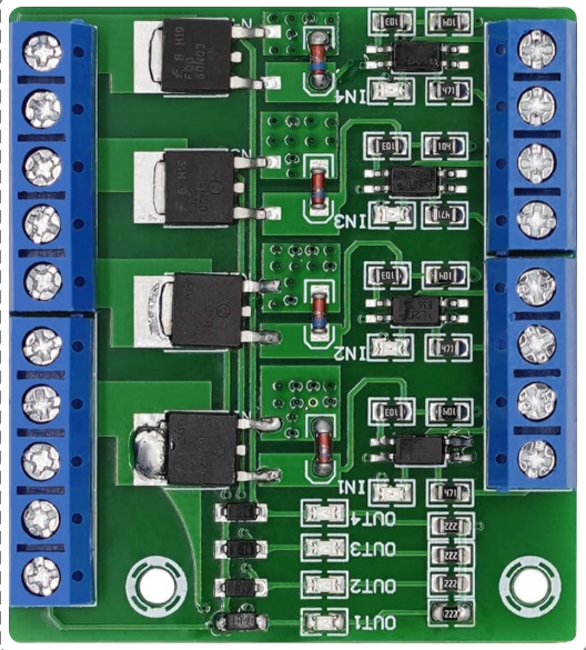
The ME60N03 4-Channel MOSFET is a high-performance N-channel MOSFET designed for efficient switching applications. It features four channels for parallel operation, making it ideal for power management and control in various electronic circuits. This component is widely used in applications requiring high-speed switching, low power loss, and high current handling capabilities.

Explore Projects Built with ME60N03 4-Channel Mosfet 3

Use Cirkit Designer to design, explore, and prototype these projects online. Some projects support real-time simulation. Click "Open Project" to start designing instantly!
STM32 Nucleo-Controlled Solenoid Actuation System
Image of stm32 braile: A project utilizing ME60N03 4-Channel Mosfet 3 in a practical application
This circuit appears to be a microcontroller-driven array of push-pull solenoids with flyback diodes for protection. The STM32 Nucleo F303RE microcontroller's GPIO pins are connected to the gates of several nMOS transistors, which act as switches to control the current flow to the solenoids. A pushbutton with a pull-up resistor is also interfaced with the microcontroller for user input, and the power supply is connected to the solenoids with ground return paths through the nMOS transistors.
Cirkit Designer LogoOpen Project in Cirkit Designer
Arduino UNO Controlled nMOS Transistor Array with Resistor Network
Image of elka_1: A project utilizing ME60N03 4-Channel Mosfet 3 in a practical application
This circuit uses an Arduino UNO to control three nMOS transistors via three 1k Ohm resistors connected to digital pins D3, D6, and D9. The transistors' sources are tied to ground, and their gates are driven by the Arduino to switch the transistors on and off, likely for controlling high-power loads or other devices.
Cirkit Designer LogoOpen Project in Cirkit Designer
Pixhawk-Controlled Solenoid Driver with Voltage Regulation
Image of solenoid control circuit: A project utilizing ME60N03 4-Channel Mosfet 3 in a practical application
This circuit uses an LM393 comparator to drive an IRFZ44N MOSFET based on the comparison between two input signals from a pixhawk 2.4.8 flight controller. The MOSFET switches a solenoid, with a diode for back EMF protection, and the system is powered by a Lipo battery with voltage regulation provided by a step-up boost converter and a step-down voltage regulator to ensure stable operation. A resistor is connected to the gate of the MOSFET for proper biasing.
Cirkit Designer LogoOpen Project in Cirkit Designer
Dual Motor Control Circuit with LED Indicator and Adjustable Speed
Image of Simple Drone: A project utilizing ME60N03 4-Channel Mosfet 3 in a practical application
This circuit is designed to control the speed and direction of coreless motors using MOSFETs, with a potentiometer providing adjustable speed control for one direction. A rocker switch enables power control, and a red LED serves as a power indicator. Diodes are included for motor back-EMF protection.
Cirkit Designer LogoOpen Project in Cirkit Designer

Explore Projects Built with ME60N03 4-Channel Mosfet 3

Use Cirkit Designer to design, explore, and prototype these projects online. Some projects support real-time simulation. Click "Open Project" to start designing instantly!
Image of stm32 braile: A project utilizing ME60N03 4-Channel Mosfet 3 in a practical application
STM32 Nucleo-Controlled Solenoid Actuation System
This circuit appears to be a microcontroller-driven array of push-pull solenoids with flyback diodes for protection. The STM32 Nucleo F303RE microcontroller's GPIO pins are connected to the gates of several nMOS transistors, which act as switches to control the current flow to the solenoids. A pushbutton with a pull-up resistor is also interfaced with the microcontroller for user input, and the power supply is connected to the solenoids with ground return paths through the nMOS transistors.
Cirkit Designer LogoOpen Project in Cirkit Designer
Image of elka_1: A project utilizing ME60N03 4-Channel Mosfet 3 in a practical application
Arduino UNO Controlled nMOS Transistor Array with Resistor Network
This circuit uses an Arduino UNO to control three nMOS transistors via three 1k Ohm resistors connected to digital pins D3, D6, and D9. The transistors' sources are tied to ground, and their gates are driven by the Arduino to switch the transistors on and off, likely for controlling high-power loads or other devices.
Cirkit Designer LogoOpen Project in Cirkit Designer
Image of solenoid control circuit: A project utilizing ME60N03 4-Channel Mosfet 3 in a practical application
Pixhawk-Controlled Solenoid Driver with Voltage Regulation
This circuit uses an LM393 comparator to drive an IRFZ44N MOSFET based on the comparison between two input signals from a pixhawk 2.4.8 flight controller. The MOSFET switches a solenoid, with a diode for back EMF protection, and the system is powered by a Lipo battery with voltage regulation provided by a step-up boost converter and a step-down voltage regulator to ensure stable operation. A resistor is connected to the gate of the MOSFET for proper biasing.
Cirkit Designer LogoOpen Project in Cirkit Designer
Image of Simple Drone: A project utilizing ME60N03 4-Channel Mosfet 3 in a practical application
Dual Motor Control Circuit with LED Indicator and Adjustable Speed
This circuit is designed to control the speed and direction of coreless motors using MOSFETs, with a potentiometer providing adjustable speed control for one direction. A rocker switch enables power control, and a red LED serves as a power indicator. Diodes are included for motor back-EMF protection.
Cirkit Designer LogoOpen Project in Cirkit Designer

Common Applications

  • Motor control and driver circuits
  • DC-DC converters
  • Power management in embedded systems
  • LED drivers
  • Battery management systems

Technical Specifications

Key Specifications

Parameter Value
Type N-Channel MOSFET
Number of Channels 4
Maximum Drain-Source Voltage (VDS) 30V
Maximum Gate-Source Voltage (VGS) ±20V
Continuous Drain Current (ID) 60A (per channel)
Maximum Power Dissipation (PD) 150W
RDS(on) (Drain-Source On Resistance) 0.012Ω (typical)
Operating Temperature Range -55°C to +175°C
Package Type TO-220

Pin Configuration and Descriptions

The ME60N03 4-Channel MOSFET is typically housed in a TO-220 package. Below is the pin configuration:

Pin Number Pin Name Description
1 Gate 1 Gate terminal for Channel 1
2 Gate 2 Gate terminal for Channel 2
3 Gate 3 Gate terminal for Channel 3
4 Gate 4 Gate terminal for Channel 4
5 Drain Common drain terminal for all channels
6 Source Common source terminal for all channels

Usage Instructions

How to Use the ME60N03 in a Circuit

  1. Power Supply Considerations: Ensure the supply voltage does not exceed the maximum VDS (30V) or VGS (±20V) ratings.
  2. Gate Drive: Use a gate driver or microcontroller to control the gate terminals. A voltage of 10V is typically recommended for full enhancement.
  3. Parallel Operation: The four channels can be used in parallel to handle higher currents. Ensure proper heat dissipation when operating at high power.
  4. Load Connection: Connect the load between the drain and the positive supply voltage. The source terminal should be connected to ground.

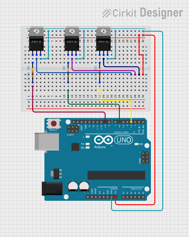
Example Circuit with Arduino UNO

Below is an example of how to control one channel of the ME60N03 using an Arduino UNO to drive a motor:

Circuit Connections

  • Connect the Gate 1 pin to Arduino digital pin 9 through a 220Ω resistor.
  • Connect the Drain pin to one terminal of the motor.
  • Connect the other terminal of the motor to the positive supply voltage (e.g., 12V).
  • Connect the Source pin to ground.

Arduino Code

// Example code to control the ME60N03 MOSFET with Arduino UNO
// This code turns the motor ON for 2 seconds and OFF for 2 seconds.

const int mosfetGatePin = 9; // Pin connected to Gate 1 of the MOSFET

void setup() {
  pinMode(mosfetGatePin, OUTPUT); // Set the MOSFET gate pin as output
}

void loop() {
  digitalWrite(mosfetGatePin, HIGH); // Turn the MOSFET ON (motor ON)
  delay(2000); // Wait for 2 seconds
  digitalWrite(mosfetGatePin, LOW);  // Turn the MOSFET OFF (motor OFF)
  delay(2000); // Wait for 2 seconds
}

Important Considerations

  • Heat Dissipation: Use a heatsink with the TO-220 package to prevent overheating during high-current operation.
  • Gate Resistor: Always use a resistor (e.g., 220Ω) between the microcontroller and the gate to limit inrush current and protect the microcontroller.
  • Flyback Diode: When driving inductive loads (e.g., motors), include a flyback diode across the load to protect the MOSFET from voltage spikes.

Troubleshooting and FAQs

Common Issues and Solutions

  1. MOSFET Overheating

    • Cause: Insufficient heat dissipation or excessive current.
    • Solution: Attach a heatsink to the TO-220 package and ensure the current is within the rated limits.
  2. MOSFET Not Switching

    • Cause: Insufficient gate voltage or incorrect wiring.
    • Solution: Verify that the gate voltage is at least 10V for full enhancement. Check all connections.
  3. Load Not Operating

    • Cause: Incorrect load connection or damaged MOSFET.
    • Solution: Ensure the load is properly connected between the drain and the positive supply. Test the MOSFET with a multimeter.
  4. Arduino Resetting

    • Cause: High inrush current from the gate damaging the microcontroller.
    • Solution: Use a gate resistor (e.g., 220Ω) to limit the current.

FAQs

Q1: Can I use the ME60N03 with a 3.3V microcontroller?
A1: The ME60N03 requires a gate voltage of at least 10V for full enhancement. Use a gate driver circuit to step up the 3.3V signal.

Q2: Can I use all four channels simultaneously?
A2: Yes, the four channels can be used in parallel to handle higher currents. Ensure proper heat dissipation and balanced current sharing.

Q3: What is the maximum current the ME60N03 can handle?
A3: Each channel can handle up to 60A. When using all four channels in parallel, the total current capacity is 240A, provided proper cooling is implemented.

Q4: Is the ME60N03 suitable for high-frequency switching?
A4: Yes, the ME60N03 is designed for high-speed switching applications. However, ensure the gate driver can handle the required switching frequency.