
How to Use bipin : Examples, Pinouts, and Specs
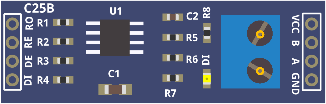
 Design with bipin in Cirkit Designer
Introduction
A bipin is a type of electrical connector featuring two pins, typically used for connecting light bulbs and other electronic devices. Its design allows for easy insertion and removal, making it a popular choice in applications where frequent replacement or maintenance is required. Bipins are commonly found in halogen lamps, LED bulbs, and fluorescent tubes, and they are available in various sizes and pin spacings to suit different devices.
Explore Projects Built with bipin
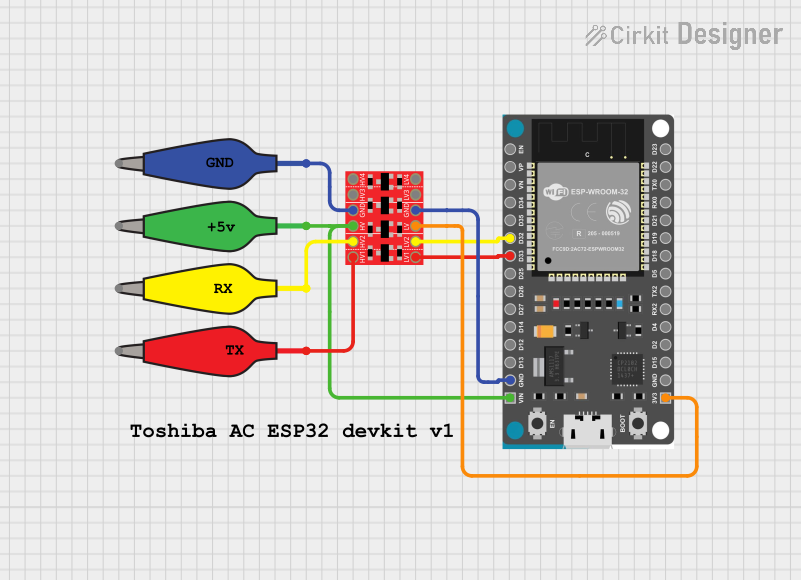 Open Project in Cirkit Designer
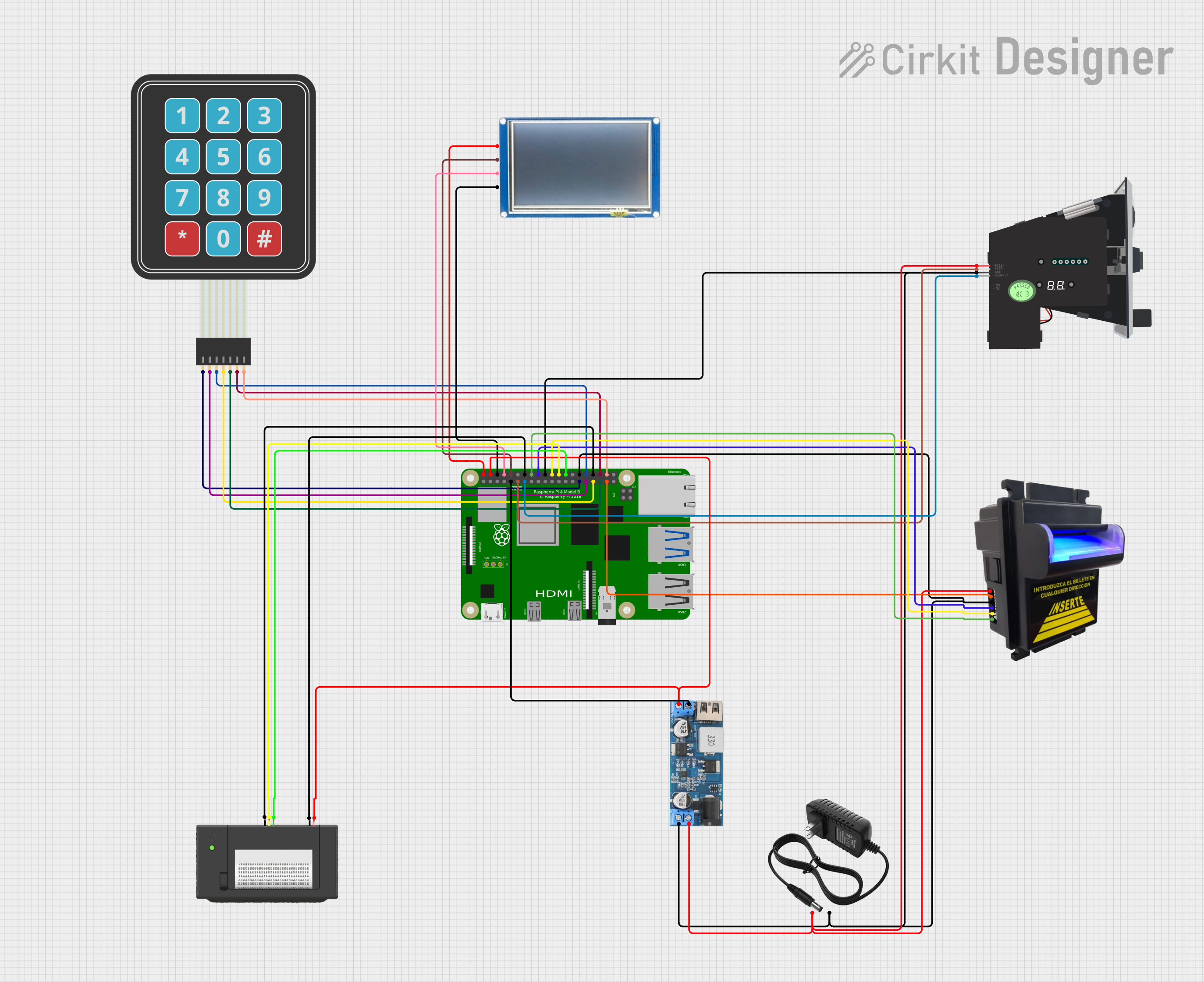 Open Project in Cirkit Designer
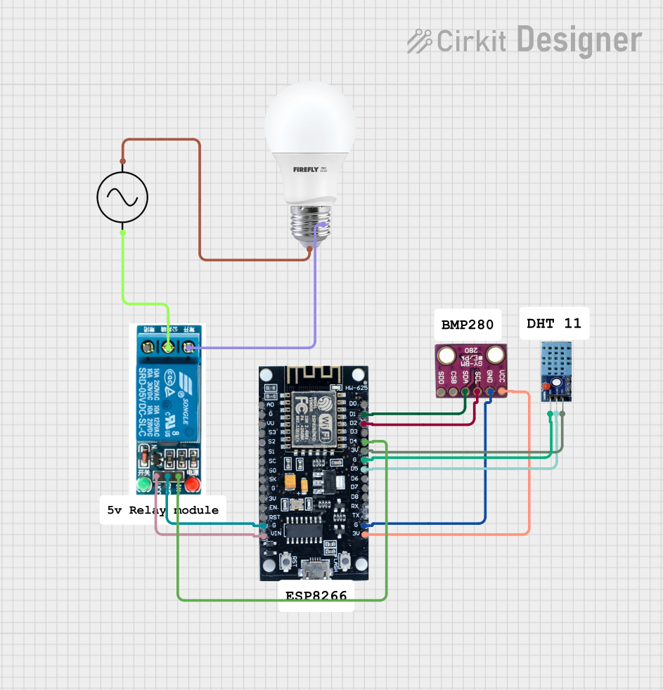 Open Project in Cirkit Designer
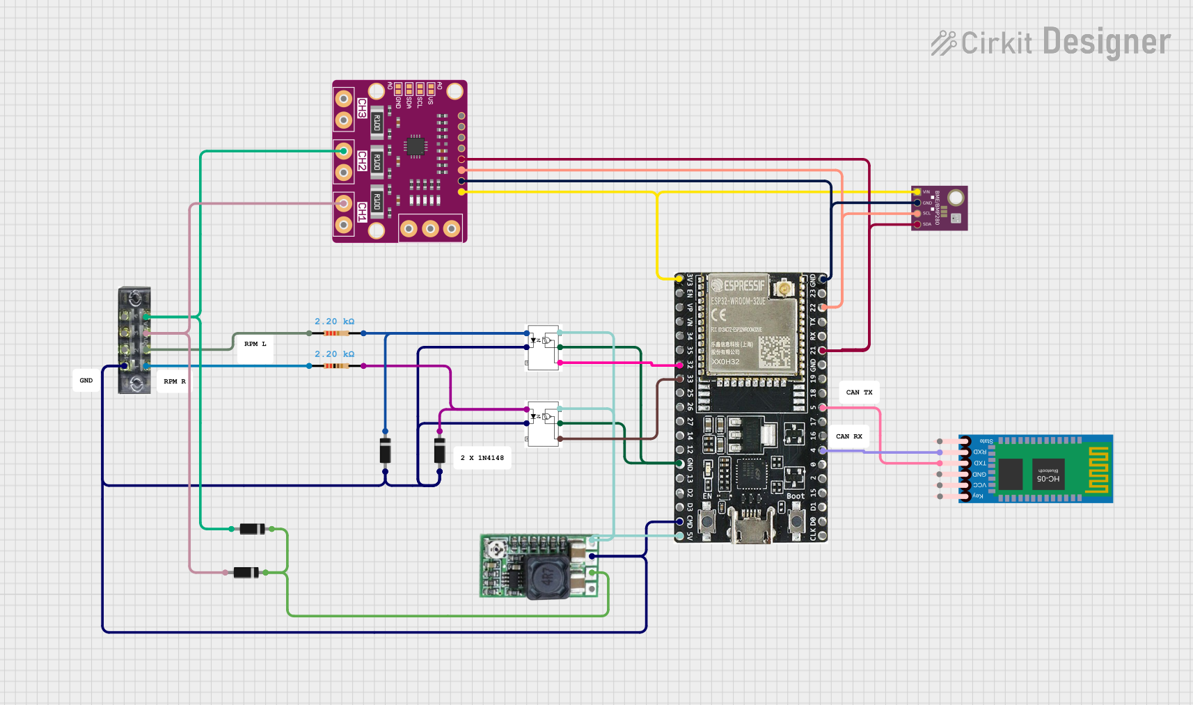 Open Project in Cirkit Designer
Explore Projects Built with bipin
Open Project in Cirkit DesignerOpen Project in Cirkit DesignerOpen Project in Cirkit DesignerOpen Project in Cirkit DesignerCommon Applications
- Halogen and LED light bulbs
- Fluorescent tube lighting
- Stage and studio lighting
- Automotive lighting systems
- Small electronic devices requiring compact connectors
Technical Specifications
The technical specifications of a bipin connector can vary depending on the specific type and application. Below are general specifications for standard bipin connectors:
General Specifications
| Parameter | Value/Range |
|---|---|
| Pin Spacing | 4 mm to 10 mm (varies by type) |
| Voltage Rating | 12V, 24V, 120V, or 240V |
| Current Rating | 1A to 10A |
| Material | Brass or copper (pins), ceramic or plastic (base) |
| Operating Temperature | -20°C to 120°C |
| Lifespan | 1,000 to 50,000 hours (depends on application) |
Pin Configuration
The bipin connector has two pins, typically labeled as follows:
| Pin Number | Description |
|---|---|
| Pin 1 | Positive terminal (or live) |
| Pin 2 | Negative terminal (or neutral) |
Note: Polarity may not matter in some AC applications, such as standard light bulbs.
Usage Instructions
How to Use a Bipin Connector in a Circuit
- Identify the Bipin Type: Determine the pin spacing and voltage rating of the bipin connector to ensure compatibility with your device.
- Insert the Bipin: Align the two pins with the corresponding socket or holder and gently push the connector into place. Ensure a snug fit for proper electrical contact.
- Connect to Power: If wiring is required, connect the positive and negative terminals to the appropriate power source. Use insulated wires and connectors to prevent short circuits.
- Test the Connection: Power on the circuit and verify that the device operates as expected.
Important Considerations
- Voltage and Current Ratings: Always check the voltage and current ratings of the bipin connector to avoid overloading.
- Pin Spacing: Ensure the pin spacing matches the socket to prevent loose connections or damage.
- Heat Management: For high-power applications, ensure adequate ventilation or heat dissipation to prevent overheating.
- Polarity: In DC circuits, ensure correct polarity to avoid damage to the device.
Example: Using a Bipin LED Bulb with an Arduino UNO
If you are using a bipin LED bulb with an Arduino UNO, you can control it via a relay module. Below is an example code snippet:
// Example: Controlling a Bipin LED Bulb with Arduino UNO
// This code uses a relay module to switch the bulb on and off.

const int relayPin = 7; // Pin connected to the relay module

void setup() {
  pinMode(relayPin, OUTPUT); // Set relay pin as output
  digitalWrite(relayPin, LOW); // Ensure relay is off at startup
}

void loop() {
  digitalWrite(relayPin, HIGH); // Turn on the bulb
  delay(1000); // Keep it on for 1 second
  digitalWrite(relayPin, LOW); // Turn off the bulb
  delay(1000); // Keep it off for 1 second
}
Note: Ensure the relay module is rated for the voltage and current of the bipin bulb.
Troubleshooting and FAQs
Common Issues
Loose Connection: The bipin connector may not fit snugly in the socket.
- Solution: Check for dirt or debris in the socket and clean it. Ensure the pin spacing matches the socket.
Bulb Does Not Light Up: The bulb may not receive power.
- Solution: Verify the power supply and ensure proper wiring. Check for blown fuses or tripped breakers.
Overheating: The connector or bulb becomes excessively hot.
- Solution: Ensure the voltage and current ratings are not exceeded. Improve ventilation around the bulb.
Corrosion on Pins: The pins may corrode over time, leading to poor contact.
- Solution: Clean the pins with a contact cleaner or replace the connector if necessary.
FAQs
Q: Can I use a bipin connector for both AC and DC applications?
A: Yes, bipin connectors can be used for both AC and DC applications, but ensure the voltage and current ratings are suitable for your specific use case.
Q: How do I determine the correct pin spacing for my device?
A: Refer to the device's datasheet or measure the distance between the pins on the connector or socket.
Q: Are bipin connectors interchangeable between different bulb types?
A: Not always. Ensure the pin spacing, voltage, and current ratings match the requirements of the bulb and socket.
Q: Can I solder wires directly to a bipin connector?
A: While possible, it is not recommended as it may damage the connector or reduce its lifespan. Use a compatible socket or holder instead.