How to Use 5V 10A DC: Examples, Pinouts, and Specs
Introduction
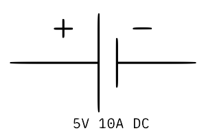
The 5V 10A DC power supply is a reliable and efficient source of direct current, delivering a stable 5 volts with a maximum current capacity of 10 amperes. This power supply is commonly used to power low-voltage electronic devices, such as microcontrollers, LED strips, single-board computers (e.g., Raspberry Pi), and other components requiring a steady 5V input. Its high current rating makes it suitable for applications that demand significant power, such as motor drivers or high-power LED arrays.
Explore Projects Built with 5V 10A DC


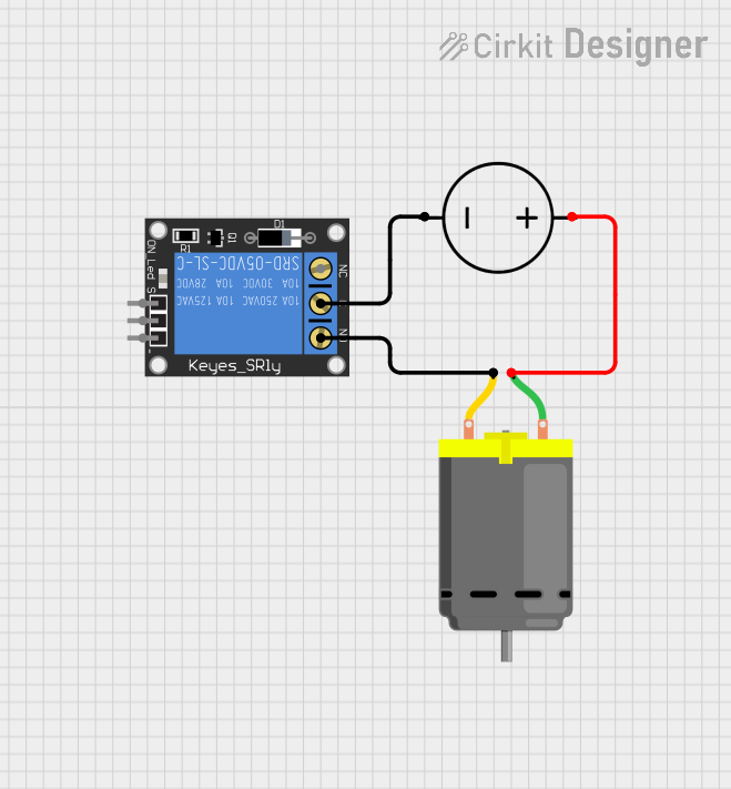
Explore Projects Built with 5V 10A DC
Technical Specifications
The following table outlines the key technical details of the 5V 10A DC power supply:
| Parameter | Specification |
|---|---|
| Input Voltage | 100-240V AC (50/60Hz) |
| Output Voltage | 5V DC |
| Maximum Output Current | 10A |
| Power Output | 50W |
| Efficiency | ≥85% |
| Ripple and Noise | ≤50mV |
| Operating Temperature | -10°C to 50°C |
| Protection Features | Overload, Overvoltage, Short Circuit |
Pin Configuration and Descriptions
The 5V 10A DC power supply typically has the following input and output connections:
Input Connections
| Pin Name | Description |
|---|---|
| L | Live AC input (100-240V AC) |
| N | Neutral AC input |
| GND | Ground (Earth) connection |
Output Connections
| Pin Name | Description |
|---|---|
| V+ | Positive DC output (5V) |
| V- | Negative DC output (Ground) |
Usage Instructions
How to Use the Component in a Circuit
Connect the Input Terminals:
- Ensure the power supply is disconnected from the AC mains before wiring.
- Connect the "L" terminal to the live wire, the "N" terminal to the neutral wire, and the "GND" terminal to the earth wire for safety.
- Double-check the connections to avoid incorrect wiring.
Connect the Output Terminals:
- Use the "V+" terminal for the positive 5V output and the "V-" terminal for the ground connection.
- Ensure the load connected to the power supply does not exceed the maximum current rating of 10A.
Power On:
- After verifying all connections, plug the power supply into the AC mains and switch it on.
- Use a multimeter to confirm the output voltage is 5V before connecting sensitive devices.
Load Connection:
- Connect your load (e.g., microcontroller, LED strip) to the output terminals.
- Ensure proper polarity to avoid damage to the connected devices.
Important Considerations and Best Practices
- Ventilation: Ensure adequate airflow around the power supply to prevent overheating.
- Current Limitation: Do not exceed the 10A current limit to avoid triggering the overload protection or damaging the power supply.
- Safety: Always disconnect the power supply from the mains before making any wiring changes.
- Fuse Protection: Use an appropriate fuse on the input side for added safety.
- Polarity: Double-check the polarity of the output connections to prevent damage to connected devices.
Example: Using the 5V 10A DC Power Supply with an Arduino UNO
The 5V 10A DC power supply can be used to power an Arduino UNO and additional peripherals. Below is an example of how to connect the power supply to an Arduino UNO:
- Connect the "V+" terminal of the power supply to the 5V pin on the Arduino UNO.
- Connect the "V-" terminal of the power supply to the GND pin on the Arduino UNO.
- Ensure the total current drawn by the Arduino and peripherals does not exceed 10A.
Sample Arduino Code
// Example code to blink an LED connected to pin 13 of the Arduino UNO
// Ensure the Arduino is powered by the 5V 10A DC power supply

void setup() {
  pinMode(13, OUTPUT); // Set pin 13 as an output
}

void loop() {
  digitalWrite(13, HIGH); // Turn the LED on
  delay(1000);            // Wait for 1 second
  digitalWrite(13, LOW);  // Turn the LED off
  delay(1000);            // Wait for 1 second
}
Troubleshooting and FAQs
Common Issues and Solutions
No Output Voltage:
- Cause: Incorrect wiring or no AC input.
- Solution: Verify the input connections (L, N, and GND) and ensure the AC mains is supplying power.
Output Voltage is Not 5V:
- Cause: Load exceeding the power supply's capacity or internal fault.
- Solution: Reduce the load to within the 10A limit and recheck. If the issue persists, inspect the power supply for damage.
Power Supply Overheating:
- Cause: Insufficient ventilation or excessive load.
- Solution: Ensure proper airflow around the power supply and reduce the load if necessary.
Device Not Powering On:
- Cause: Incorrect polarity or loose connections.
- Solution: Double-check the output connections and ensure proper polarity.
FAQs
Q1: Can I use this power supply to charge a USB device?
A1: Yes, but you will need a USB adapter or module to regulate the current and provide the appropriate USB connector.
Q2: Is this power supply suitable for outdoor use?
A2: No, this power supply is designed for indoor use only. Use a weatherproof enclosure if outdoor operation is required.
Q3: What happens if I exceed the 10A current limit?
A3: The power supply's overload protection will activate, shutting down the output to prevent damage. Reduce the load and restart the power supply.
Q4: Can I use this power supply with a Raspberry Pi?
A4: Yes, the 5V 10A DC power supply is suitable for powering a Raspberry Pi. Ensure proper connections and use a fuse for added protection.