
How to Use USB Connectors: Examples, Pinouts, and Specs
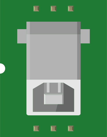
 Design with USB Connectors in Cirkit Designer
Introduction
USB connectors are standardized interfaces used for connecting devices to computers and power sources, allowing for data transfer and charging. They are widely used in consumer electronics, including smartphones, laptops, printers, external storage devices, and more. USB connectors come in various types and sizes, such as USB-A, USB-B, USB-C, and Micro-USB, each designed for specific applications and compatibility.
Common applications of USB connectors include:
- Data transfer between devices (e.g., file sharing, syncing).
- Charging electronic devices (e.g., smartphones, tablets, power banks).
- Connecting peripherals like keyboards, mice, and printers to computers.
- Powering small electronic devices and development boards.
Explore Projects Built with USB Connectors
 Open Project in Cirkit Designer
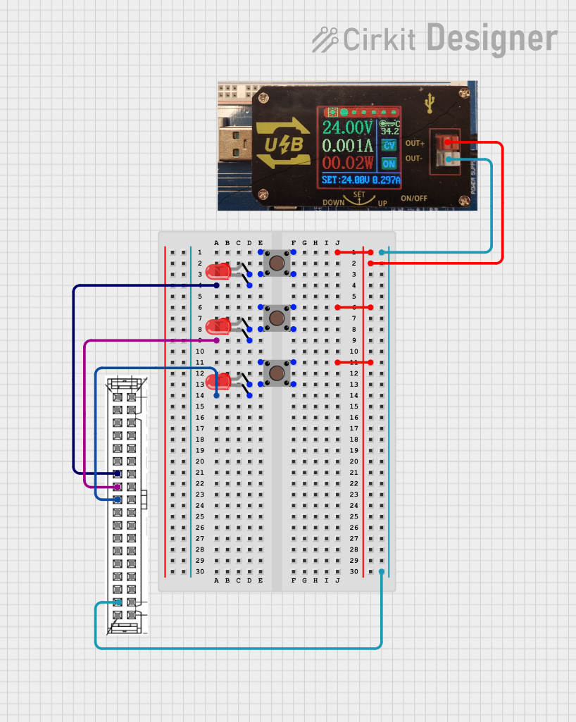 Open Project in Cirkit Designer
 Open Project in Cirkit Designer
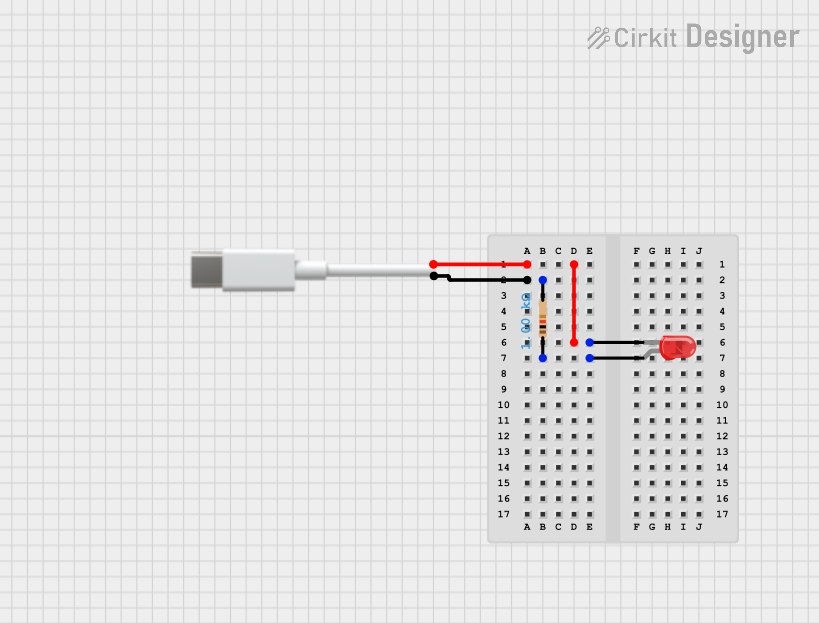 Open Project in Cirkit Designer
Explore Projects Built with USB Connectors
Open Project in Cirkit DesignerOpen Project in Cirkit DesignerOpen Project in Cirkit DesignerOpen Project in Cirkit DesignerTechnical Specifications
General Specifications
- Voltage Rating: 5V (standard), with support for higher voltages in USB Power Delivery (USB-PD).
- Current Rating: Typically 500mA to 3A, depending on the USB version and connector type.
- Data Transfer Speeds:
- USB 2.0: Up to 480 Mbps
- USB 3.0: Up to 5 Gbps
- USB 3.1: Up to 10 Gbps
- USB 3.2 and USB4: Up to 40 Gbps
- Operating Temperature: -20°C to 85°C (varies by manufacturer).
Pin Configuration and Descriptions
USB Type-A Connector (Standard)
| Pin Number | Name | Description |
|---|---|---|
| 1 | VBUS | +5V power supply |
| 2 | D- | Data line (negative) |
| 3 | D+ | Data line (positive) |
| 4 | GND | Ground |
USB Type-C Connector
| Pin Number | Name | Description |
|---|---|---|
| A1, B12 | GND | Ground |
| A4, B9 | VBUS | +5V power supply |
| A6, B6 | D+ | Data line (positive) |
| A7, B7 | D- | Data line (negative) |
| A2, B11 | TX+ | SuperSpeed differential pair (positive) |
| A3, B10 | TX- | SuperSpeed differential pair (negative) |
| A8, B5 | RX+ | SuperSpeed differential pair (positive) |
| A9, B4 | RX- | SuperSpeed differential pair (negative) |
Usage Instructions
How to Use USB Connectors in a Circuit
- Identify the Connector Type: Determine the type of USB connector (e.g., USB-A, USB-C) required for your application.
- Connect Power and Ground: Ensure the VBUS pin is connected to a regulated 5V power source and the GND pin is connected to the circuit ground.
- Connect Data Lines: For data transfer, connect the D+ and D- pins to the corresponding data lines of your device or microcontroller.
- Use Proper Pull-Up/Pull-Down Resistors: For USB communication, ensure proper termination resistors are used as per the USB specification.
- Secure the Connector: Mount the USB connector securely on the PCB or enclosure to prevent mechanical stress.
Important Considerations and Best Practices
- Voltage Regulation: Ensure the power supply to the VBUS pin is stable and within the USB voltage range (4.75V to 5.25V).
- Cable Quality: Use high-quality USB cables to minimize data loss and ensure reliable power delivery.
- Overcurrent Protection: Include a fuse or current-limiting circuit to protect against overcurrent conditions.
- USB-C Orientation: USB-C connectors are reversible, so ensure your circuit supports both orientations if required.
Example: Connecting a USB Connector to an Arduino UNO
Below is an example of using a USB Type-B connector to power and communicate with an Arduino UNO.
// Example: Reading data from a USB-connected device using Arduino UNO
// Ensure the USB Type-B connector is properly wired to the Arduino UNO.

void setup() {
  Serial.begin(9600); // Initialize serial communication at 9600 baud
  while (!Serial) {
    // Wait for the serial port to connect (only needed for native USB boards)
  }
  Serial.println("USB connection established.");
}

void loop() {
  if (Serial.available() > 0) {
    // Read incoming data from the USB connection
    char receivedData = Serial.read();
    Serial.print("Received: ");
    Serial.println(receivedData);
  }
}
Troubleshooting and FAQs
Common Issues
No Power or Device Not Recognized:
- Cause: Loose connection or damaged cable.
- Solution: Check the USB cable and connector for physical damage. Ensure the connector is securely plugged in.
Data Transfer Errors:
- Cause: Poor-quality cable or incorrect wiring of data lines.
- Solution: Use a certified USB cable and verify the D+ and D- connections.
Overheating:
- Cause: Excessive current draw or short circuit.
- Solution: Check for short circuits and ensure the current draw does not exceed the connector's rating.
USB-C Orientation Issues:
- Cause: Circuit not designed for reversible USB-C connections.
- Solution: Use a USB-C controller IC to handle orientation.
FAQs
Q: Can I use a USB connector for both power and data simultaneously?
A: Yes, USB connectors are designed to handle both power and data transfer simultaneously.Q: What is the maximum current supported by USB-C?
A: USB-C supports up to 3A at 5V by default and up to 5A with USB Power Delivery (USB-PD).Q: How do I identify the pinout of a USB connector?
A: Refer to the datasheet or use a multimeter to trace the connections. Pinouts are standardized for each USB type.Q: Can I use a USB connector to power a microcontroller?
A: Yes, many microcontrollers, such as Arduino boards, can be powered via the USB VBUS pin. Ensure the current requirements are met.