Cirkit Designer Logo
Cirkit Designer
Your all-in-one circuit design IDE
Home / 
Component Documentation

How to Use VY-102BK: Examples, Pinouts, and Specs

Image of VY-102BK
Cirkit Designer LogoDesign with VY-102BK in Cirkit Designer

Introduction

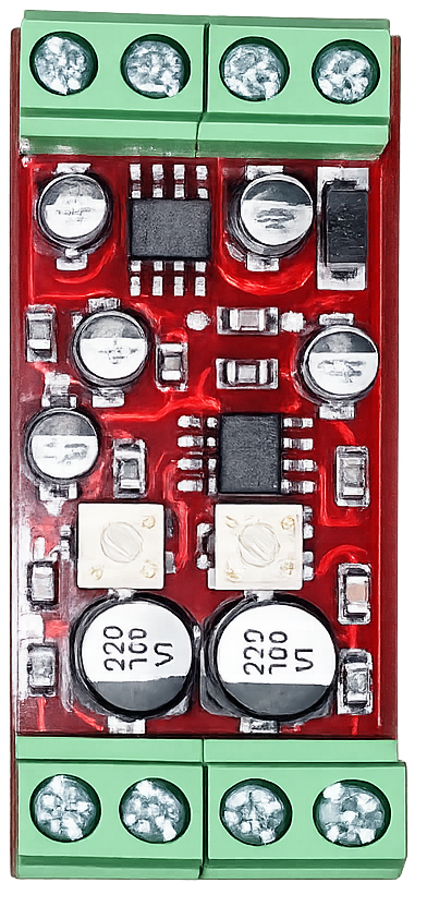
The VY-102BK is a versatile relay switch manufactured by Base. It is designed to control high-power devices using low-power signals, making it an essential component in automation, home appliances, and industrial control systems. Its compact design and reliable performance ensure seamless integration into a wide range of electronic applications.

Explore Projects Built with VY-102BK

Use Cirkit Designer to design, explore, and prototype these projects online. Some projects support real-time simulation. Click "Open Project" to start designing instantly!
Arduino Pro Mini-Based Battery-Powered Laser Emitter with Temperature Sensing and OLED Display
Image of temp gun: A project utilizing VY-102BK in a practical application
This circuit is a sensor and display system powered by a 9V battery, featuring an Arduino Pro Mini microcontroller. It includes a momentary switch to control power, a KY-008 laser emitter, an MLX90614 temperature sensor, and an OLED display for output. The system is designed to read temperature data and display it on the OLED screen, with the laser emitter potentially used for targeting or indication purposes.
Cirkit Designer LogoOpen Project in Cirkit Designer
Voice-Controlled Buzzer System with VC-02 Module
Image of vc: A project utilizing VY-102BK in a practical application
This circuit features a VC-02 voice recognition module connected to a buzzer and powered by a 5V battery. The VC-02 module is programmed to listen for specific voice commands and, upon recognizing the command 'can you make a sound', it activates the buzzer for one second. The circuit is designed for voice-activated sound generation, with the VC-02 module handling voice recognition and serial communication, and the buzzer providing audible feedback.
Cirkit Designer LogoOpen Project in Cirkit Designer
ESP32 and Logic Level Converter-Based Wi-Fi Controlled Interface
Image of Toshiba AC ESP32 devkit v1: A project utilizing VY-102BK in a practical application
This circuit features an ESP32 Devkit V1 microcontroller connected to a Bi-Directional Logic Level Converter, which facilitates voltage level shifting between the ESP32 and external components. The ESP32 is powered through its VIN pin via an alligator clip cable, and the logic level converter is connected to various pins on the ESP32 to manage different voltage levels for communication.
Cirkit Designer LogoOpen Project in Cirkit Designer
Arduino Nano-Based Multi-Zone Soil Moisture Monitor with OLED Display
Image of Soil Moisture Sensor Analog: A project utilizing VY-102BK in a practical application
This circuit is designed to collect environmental data using multiple YL-83 modules with YL-69 sondas for soil moisture, and a KY-015 DHT11 sensor for humidity and temperature, all interfaced with an Arduino Nano. Data from the sensors is processed by the Arduino and displayed on an OLED screen, with power supplied by an MB102 Breadboard Power Supply Module.
Cirkit Designer LogoOpen Project in Cirkit Designer

Explore Projects Built with VY-102BK

Use Cirkit Designer to design, explore, and prototype these projects online. Some projects support real-time simulation. Click "Open Project" to start designing instantly!
Image of temp gun: A project utilizing VY-102BK in a practical application
Arduino Pro Mini-Based Battery-Powered Laser Emitter with Temperature Sensing and OLED Display
This circuit is a sensor and display system powered by a 9V battery, featuring an Arduino Pro Mini microcontroller. It includes a momentary switch to control power, a KY-008 laser emitter, an MLX90614 temperature sensor, and an OLED display for output. The system is designed to read temperature data and display it on the OLED screen, with the laser emitter potentially used for targeting or indication purposes.
Cirkit Designer LogoOpen Project in Cirkit Designer
Image of vc: A project utilizing VY-102BK in a practical application
Voice-Controlled Buzzer System with VC-02 Module
This circuit features a VC-02 voice recognition module connected to a buzzer and powered by a 5V battery. The VC-02 module is programmed to listen for specific voice commands and, upon recognizing the command 'can you make a sound', it activates the buzzer for one second. The circuit is designed for voice-activated sound generation, with the VC-02 module handling voice recognition and serial communication, and the buzzer providing audible feedback.
Cirkit Designer LogoOpen Project in Cirkit Designer
Image of Toshiba AC ESP32 devkit v1: A project utilizing VY-102BK in a practical application
ESP32 and Logic Level Converter-Based Wi-Fi Controlled Interface
This circuit features an ESP32 Devkit V1 microcontroller connected to a Bi-Directional Logic Level Converter, which facilitates voltage level shifting between the ESP32 and external components. The ESP32 is powered through its VIN pin via an alligator clip cable, and the logic level converter is connected to various pins on the ESP32 to manage different voltage levels for communication.
Cirkit Designer LogoOpen Project in Cirkit Designer
Image of Soil Moisture Sensor Analog: A project utilizing VY-102BK in a practical application
Arduino Nano-Based Multi-Zone Soil Moisture Monitor with OLED Display
This circuit is designed to collect environmental data using multiple YL-83 modules with YL-69 sondas for soil moisture, and a KY-015 DHT11 sensor for humidity and temperature, all interfaced with an Arduino Nano. Data from the sensors is processed by the Arduino and displayed on an OLED screen, with power supplied by an MB102 Breadboard Power Supply Module.
Cirkit Designer LogoOpen Project in Cirkit Designer

Common Applications

  • Home automation systems (e.g., controlling lights, fans, or appliances)
  • Industrial machinery control
  • Automotive electronics
  • Microcontroller-based projects (e.g., Arduino, Raspberry Pi)
  • Power management systems

Technical Specifications

Key Specifications

Parameter Value
Manufacturer Base
Part ID VY-102BK
Relay Type Electromechanical
Operating Voltage 5V DC
Switching Voltage Up to 250V AC / 30V DC
Switching Current Up to 10A
Coil Resistance 70Ω ±10%
Contact Configuration SPDT (Single Pole Double Throw)
Dimensions 19mm x 15mm x 15mm
Operating Temperature -40°C to +85°C
Insulation Resistance ≥100MΩ at 500V DC
Dielectric Strength 1500V AC for 1 minute

Pin Configuration

The VY-102BK relay has 5 pins, as described in the table below:

Pin Number Name Description
1 Coil (+) Positive terminal of the relay coil
2 Coil (-) Negative terminal of the relay coil
3 Common (COM) Common terminal for the switching mechanism
4 Normally Open (NO) Connected to COM when the relay is activated
5 Normally Closed (NC) Connected to COM when the relay is inactive

Usage Instructions

How to Use the VY-102BK in a Circuit

  1. Power the Relay Coil: Connect the coil pins (1 and 2) to a 5V DC power source. Use a transistor or MOSFET to control the coil with a microcontroller.
  2. Connect the Load:
    • Connect the load to the COM pin (Pin 3).
    • Use the NO pin (Pin 4) if you want the load to be powered only when the relay is activated.
    • Use the NC pin (Pin 5) if you want the load to be powered when the relay is inactive.
  3. Control the Relay: Use a low-power signal (e.g., from an Arduino) to activate the relay coil, which will switch the load between the NO and NC terminals.

Important Considerations

  • Diode Protection: Always connect a flyback diode across the coil terminals to protect the circuit from voltage spikes when the relay is deactivated.
  • Current Ratings: Ensure the load current does not exceed the relay's maximum switching current (10A).
  • Isolation: Use optocouplers or isolation circuits if the relay is controlling high-voltage devices.

Example: Connecting the VY-102BK to an Arduino UNO

Below is an example of how to control the VY-102BK relay using an Arduino UNO:

// Define the pin connected to the relay control transistor
const int relayPin = 7;

void setup() {
  pinMode(relayPin, OUTPUT); // Set the relay pin as an output
  digitalWrite(relayPin, LOW); // Ensure the relay is off at startup
}

void loop() {
  digitalWrite(relayPin, HIGH); // Activate the relay
  delay(5000); // Keep the relay on for 5 seconds
  digitalWrite(relayPin, LOW); // Deactivate the relay
  delay(5000); // Keep the relay off for 5 seconds
}

Note: Use a transistor (e.g., 2N2222) to drive the relay coil, as the Arduino pin cannot supply enough current directly.

Troubleshooting and FAQs

Common Issues and Solutions

  1. Relay Not Activating

    • Cause: Insufficient voltage or current to the coil.
    • Solution: Verify the power supply to the coil and ensure it provides 5V DC with sufficient current.
  2. Load Not Switching

    • Cause: Incorrect wiring of the load to the COM, NO, or NC pins.
    • Solution: Double-check the wiring and ensure the load is connected to the correct pins.
  3. Voltage Spikes Damaging Components

    • Cause: Absence of a flyback diode across the coil terminals.
    • Solution: Install a diode (e.g., 1N4007) across the coil terminals with the cathode connected to the positive terminal.
  4. Relay Buzzing or Chattering

    • Cause: Unstable control signal or insufficient coil voltage.
    • Solution: Use a stable power source and ensure the control signal is clean and consistent.

FAQs

Q1: Can the VY-102BK be used with a 3.3V microcontroller?
A1: Yes, but you will need a transistor or MOSFET to drive the 5V relay coil from the 3.3V control signal.

Q2: What is the maximum load the relay can handle?
A2: The relay can switch up to 250V AC or 30V DC with a maximum current of 10A.

Q3: Can I use the VY-102BK for DC motor control?
A3: Yes, but ensure the motor's current and voltage are within the relay's specifications. Use a flyback diode across the motor terminals to prevent voltage spikes.

Q4: Is the relay suitable for high-frequency switching?
A4: No, electromechanical relays like the VY-102BK are not ideal for high-frequency applications due to mechanical wear and slower switching speeds.