
How to Use Adafruit Push-button Power Switch Breakout: Examples, Pinouts, and Specs
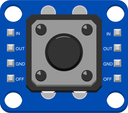
 Design with Adafruit Push-button Power Switch Breakout in Cirkit Designer
Introduction
The Adafruit Push-button Power Switch Breakout (Manufacturer Part ID: 1400) is a compact and efficient solution for controlling power to your electronic projects with a simple push-button interface. This breakout board uses a low-power MOSFET to switch high currents, making it ideal for battery-powered or low-power applications. It also features a built-in LED indicator to provide a clear visual cue of the power status.
Explore Projects Built with Adafruit Push-button Power Switch Breakout
 Open Project in Cirkit Designer
 Open Project in Cirkit Designer
 Open Project in Cirkit Designer
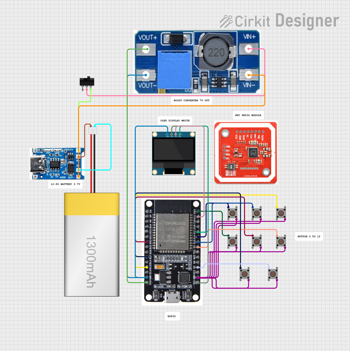 Open Project in Cirkit Designer
Explore Projects Built with Adafruit Push-button Power Switch Breakout
Open Project in Cirkit DesignerOpen Project in Cirkit DesignerOpen Project in Cirkit DesignerOpen Project in Cirkit DesignerCommon Applications and Use Cases
- Power control for battery-operated devices
- On/off control for microcontroller-based projects
- Low-power switching for portable electronics
- Projects requiring a simple and reliable power toggle mechanism
Technical Specifications
The following table outlines the key technical details of the Adafruit Push-button Power Switch Breakout:
| Parameter | Value |
|---|---|
| Operating Voltage | 1.8V to 6V DC |
| Maximum Current | Up to 3A |
| Power Indicator | Built-in LED |
| Control Mechanism | Push-button toggle |
| Dimensions | 20mm x 20mm x 3mm |
| Weight | 1.2g |
Pin Configuration and Descriptions
The breakout board has the following pin layout:
| Pin Name | Description |
|---|---|
| VIN | Input voltage (1.8V to 6V DC) |
| VOUT | Output voltage (connected to your load) |
| GND | Ground connection |
| EN | Enable pin (optional, for external control) |
| BTN | Button pin (optional, for external push-button) |
Usage Instructions
How to Use the Component in a Circuit
- Connect Power Input: Connect your power source (1.8V to 6V DC) to the
VINpin and the ground of your power source to theGNDpin. - Connect the Load: Attach the device or circuit you want to power to the
VOUTpin and its ground to theGNDpin. - Toggle Power: Use the onboard push-button to toggle the power on and off. The built-in LED will light up when the power is on.
- Optional External Button: If you want to use an external push-button, connect it to the
BTNpin and ground. Pressing the external button will toggle the power. - Optional Enable Pin: The
ENpin can be used to control the power state programmatically. Pulling this pin low will turn off the power, while leaving it floating or pulling it high will enable the power.
Important Considerations and Best Practices
- Ensure that the input voltage does not exceed 6V DC to avoid damaging the board.
- The maximum current draw should not exceed 3A to maintain safe operation.
- Use proper decoupling capacitors on the input and output if your load is sensitive to voltage fluctuations.
- If using an external button, ensure it is a momentary push-button for proper operation.
- Avoid shorting the
VINandVOUTpins, as this may damage the MOSFET.
Example: Using with an Arduino UNO
The Adafruit Push-button Power Switch Breakout can be used to control power to an Arduino UNO. Below is an example of how to connect and use the breakout board:
Wiring Diagram
- Connect the
VINpin to a 5V power source. - Connect the
VOUTpin to the Arduino UNO'sVINpin. - Connect the
GNDpin to the Arduino UNO'sGNDpin. - Optionally, connect a momentary push-button to the
BTNpin and ground.
Example Code
The following Arduino code demonstrates how to use the EN pin to programmatically control the power state:
#define EN_PIN 7  // Connect the EN pin of the breakout to Arduino pin 7

void setup() {
  pinMode(EN_PIN, OUTPUT);  // Set EN pin as an output
  digitalWrite(EN_PIN, HIGH);  // Enable power (HIGH = ON)
  delay(5000);  // Keep power on for 5 seconds
  digitalWrite(EN_PIN, LOW);  // Disable power (LOW = OFF)
}

void loop() {
  // The loop is empty as this example only demonstrates toggling power
}
Troubleshooting and FAQs
Common Issues and Solutions
The power does not toggle when pressing the button:
- Ensure the input voltage is within the specified range (1.8V to 6V DC).
- Check the connections to the
VIN,VOUT, andGNDpins. - Verify that the onboard push-button or external button is functioning properly.
The LED does not light up when power is on:
- Confirm that the load is connected correctly to the
VOUTpin. - Check if the LED is damaged or if the input voltage is too low.
- Confirm that the load is connected correctly to the
The board overheats during operation:
- Ensure the current draw of the load does not exceed 3A.
- Verify that there are no short circuits between
VINandVOUT.
The external button does not work:
- Make sure the external button is a momentary push-button.
- Check the connection between the
BTNpin and ground.
FAQs
Can I use this board with a 12V power source? No, the maximum input voltage is 6V DC. Using a higher voltage may damage the board.
Can I use this board to control AC power? No, this board is designed for DC power only. Do not use it with AC power sources.
What happens if I pull the
ENpin low? Pulling theENpin low will disable the power output, effectively turning off the connected load.Is the onboard LED removable? The onboard LED is soldered to the board and is not designed to be removed. However, you can ignore it if you do not need a visual power indicator.
This concludes the documentation for the Adafruit Push-button Power Switch Breakout. For further assistance, refer to the official Adafruit Industries website or community forums.