How to Use NPN Transistor (EBC): Examples, Pinouts, and Specs

Introduction
The NPN Transistor is a type of bipolar junction transistor (BJT) with three terminals: Emitter (E), Base (B), and Collector (C). It is widely used in electronic circuits for amplifying or switching electronic signals. The NPN transistor is a fundamental component in many analog and digital circuits, making it an essential part of any electronics enthusiast's toolkit.
Explore Projects Built with NPN Transistor (EBC)
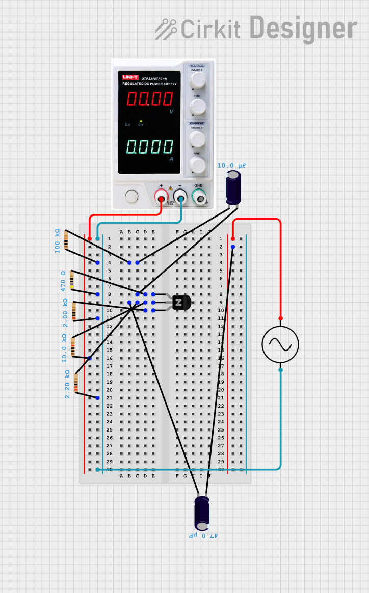
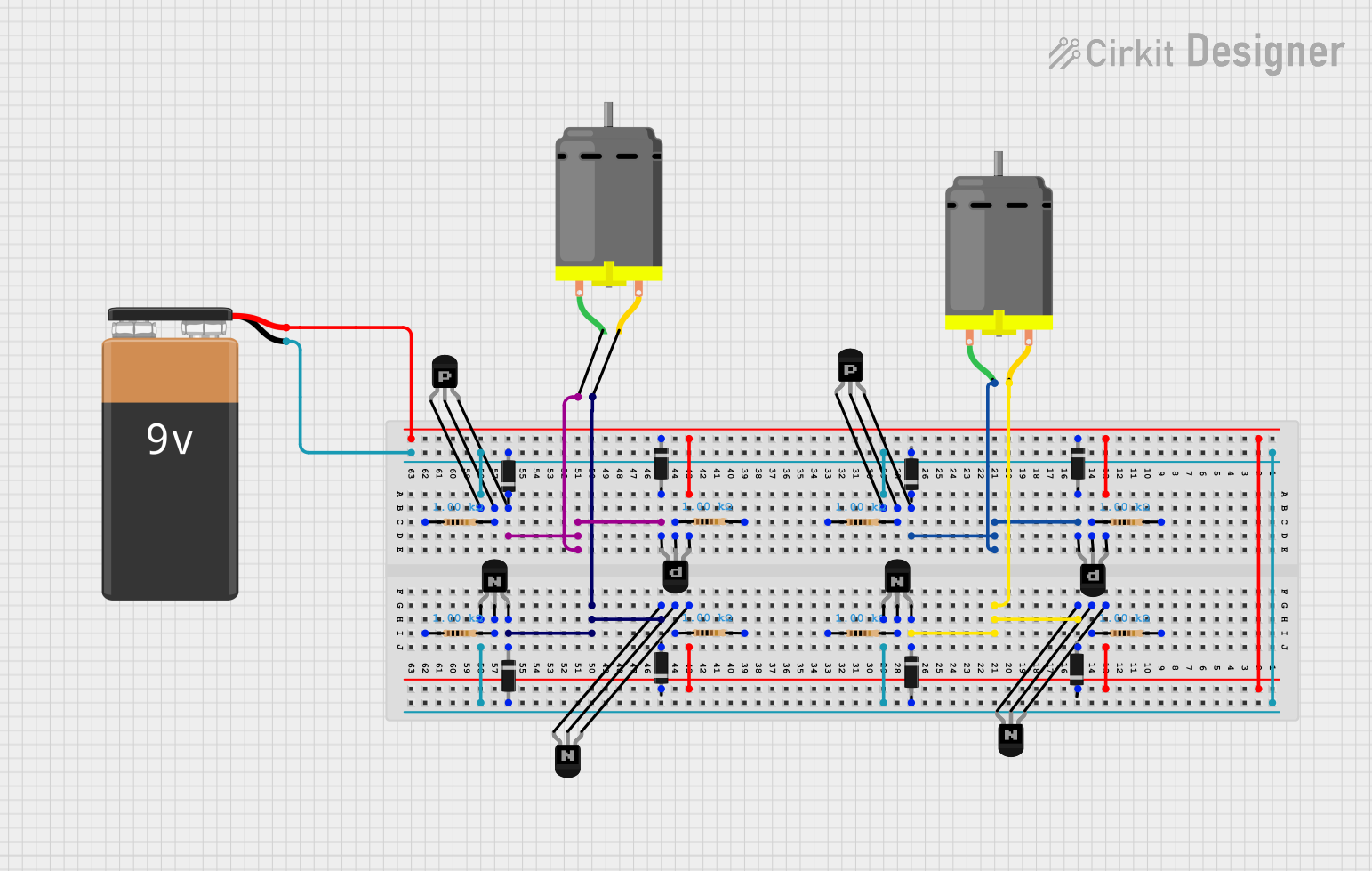
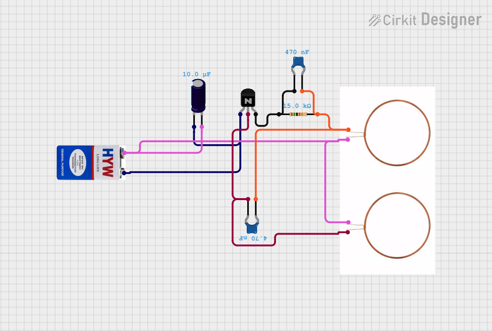
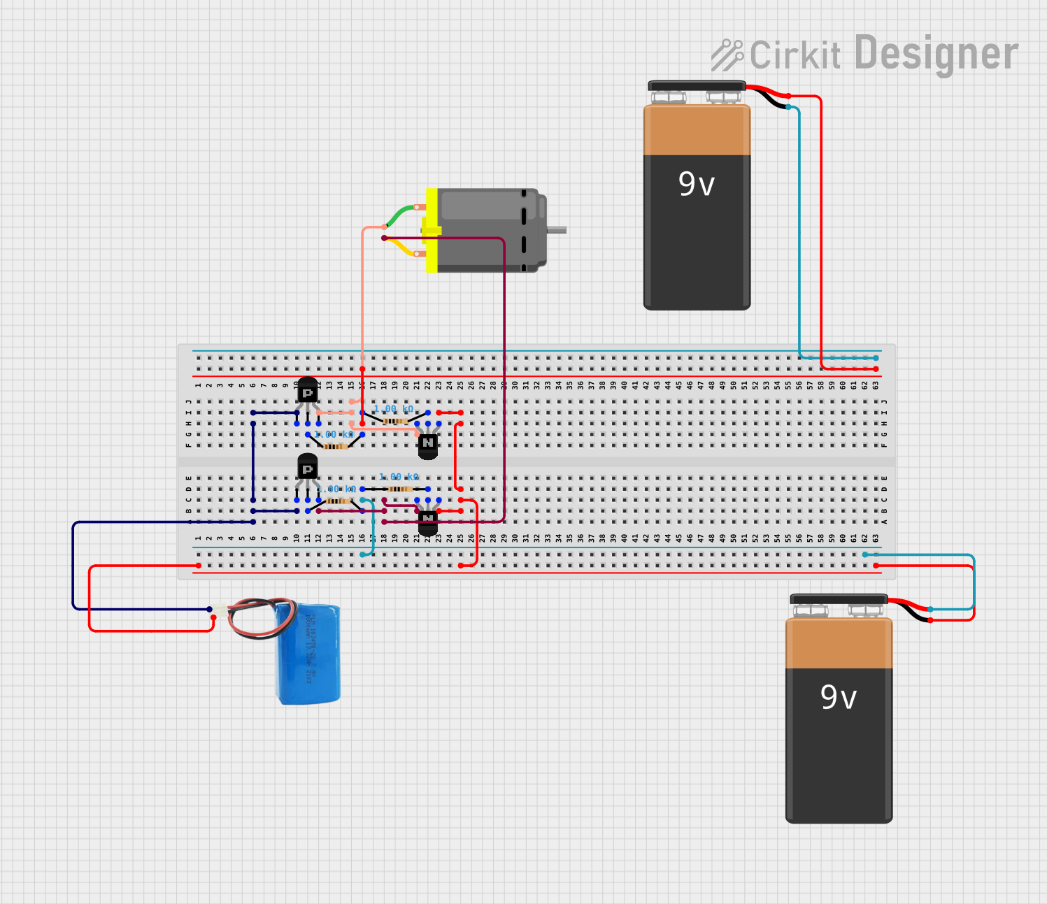
Explore Projects Built with NPN Transistor (EBC)
Common Applications and Use Cases
- Signal Amplification: Used in audio amplifiers, radio frequency amplifiers, and other signal amplification circuits.
- Switching: Employed in digital circuits, such as logic gates, microcontroller interfaces, and relay drivers.
- Oscillators: Utilized in oscillator circuits for generating periodic signals.
- Voltage Regulation: Used in voltage regulator circuits to maintain a constant output voltage.
Technical Specifications
Key Technical Details
| Parameter | Value |
|---|---|
| Type | NPN |
| Maximum Voltage | 40V |
| Maximum Current | 200mA |
| Power Dissipation | 500mW |
| Gain (hFE) | 100 - 300 |
| Package Type | TO-92 |
Pin Configuration and Descriptions
| Pin Number | Pin Name | Description |
|---|---|---|
| 1 | Emitter | The terminal through which current exits the transistor. |
| 2 | Base | The terminal that controls the transistor's operation. |
| 3 | Collector | The terminal through which current enters the transistor. |
Usage Instructions
How to Use the Component in a Circuit
- Identify the Pins: Ensure you correctly identify the Emitter (E), Base (B), and Collector (C) pins. Refer to the pin configuration table above.
- Biasing the Transistor: Apply a small current to the Base (B) to control a larger current flowing from the Collector (C) to the Emitter (E).
- Connecting in a Circuit:
- Common Emitter Configuration: Connect the Emitter to ground, the Base to the input signal through a resistor, and the Collector to the power supply through a load resistor.
- Common Collector Configuration: Connect the Collector to the power supply, the Base to the input signal through a resistor, and the Emitter to the output.
- Common Base Configuration: Connect the Base to a fixed voltage, the Emitter to the input signal, and the Collector to the output.
Important Considerations and Best Practices
- Heat Dissipation: Ensure adequate heat dissipation to prevent the transistor from overheating. Use a heat sink if necessary.
- Current Limiting: Use appropriate resistors to limit the base current and prevent damage to the transistor.
- Voltage Ratings: Do not exceed the maximum voltage and current ratings specified in the technical details.
Example Circuit with Arduino UNO
Here is an example of how to use an NPN transistor to control an LED with an Arduino UNO:
Circuit Diagram
Arduino UNO          NPN Transistor
  (Pin 9)  -------->  Base (B)
  (GND)   -------->  Emitter (E)
  (5V)    -------->  LED (Anode)
  LED (Cathode) --->  Collector (C)
Arduino Code
// Define the pin connected to the base of the NPN transistor
const int transistorBasePin = 9;

void setup() {
  // Set the transistor base pin as an output
  pinMode(transistorBasePin, OUTPUT);
}

void loop() {
  // Turn the transistor on (LED on)
  digitalWrite(transistorBasePin, HIGH);
  delay(1000); // Wait for 1 second

  // Turn the transistor off (LED off)
  digitalWrite(transistorBasePin, LOW);
  delay(1000); // Wait for 1 second
}
Troubleshooting and FAQs
Common Issues Users Might Face
Transistor Not Switching:
- Solution: Ensure the base resistor value is appropriate to provide enough base current.
- Tip: Check the connections and ensure the transistor is correctly oriented.
Overheating:
- Solution: Verify that the current through the transistor does not exceed its maximum rating.
- Tip: Use a heat sink or reduce the load current.
No Amplification:
- Solution: Ensure the transistor is properly biased.
- Tip: Check the voltage levels at the base, collector, and emitter.
FAQs
Q1: Can I use an NPN transistor to switch high voltage loads?
- A1: Yes, but ensure the voltage does not exceed the maximum voltage rating of the transistor.
Q2: How do I calculate the base resistor value?
- A2: Use the formula ( R_B = \frac{V_{in} - V_{BE}}{I_B} ), where ( V_{in} ) is the input voltage, ( V_{BE} ) is the base-emitter voltage (typically 0.7V for silicon transistors), and ( I_B ) is the desired base current.
Q3: Can I use an NPN transistor for analog signal amplification?
- A3: Yes, NPN transistors are commonly used in analog signal amplification circuits.
This documentation provides a comprehensive guide to understanding and using NPN transistors in various applications. Whether you are a beginner or an experienced user, this guide will help you effectively utilize NPN transistors in your electronic projects.