How to Use L298N: Examples, Pinouts, and Specs
Introduction
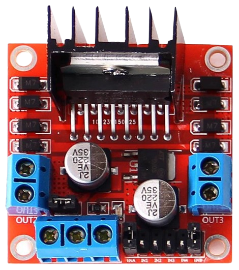
The L298N is a dual H-bridge motor driver that enables control of both the direction and speed of DC motors and stepper motors. It is capable of driving two motors simultaneously, making it a versatile and widely used component in robotics, automation, and motor control projects. The L298N is particularly popular in applications such as robotic vehicles, conveyor belts, and CNC machines due to its ability to handle high currents and its ease of integration with microcontrollers like Arduino.
Explore Projects Built with L298N
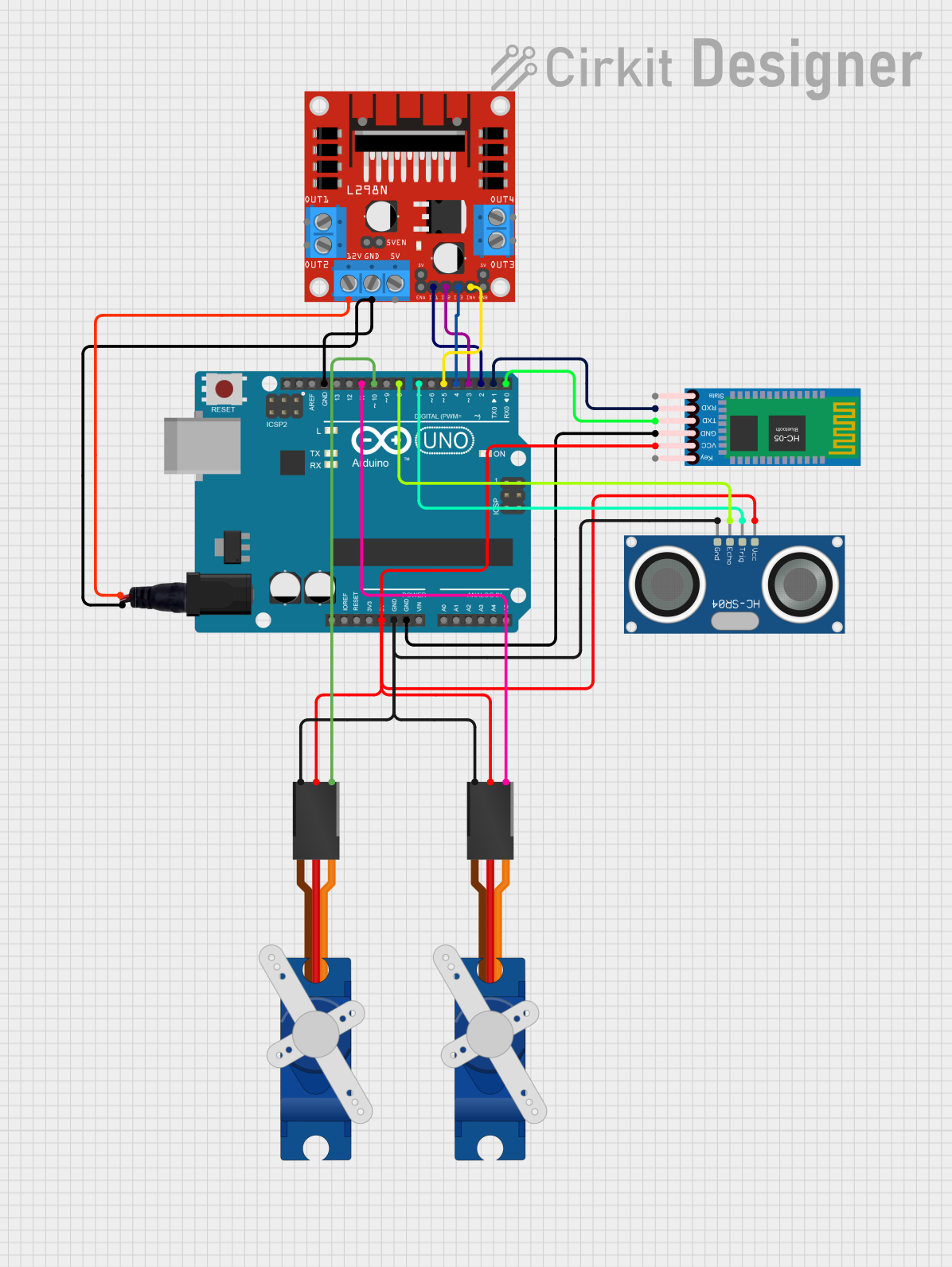
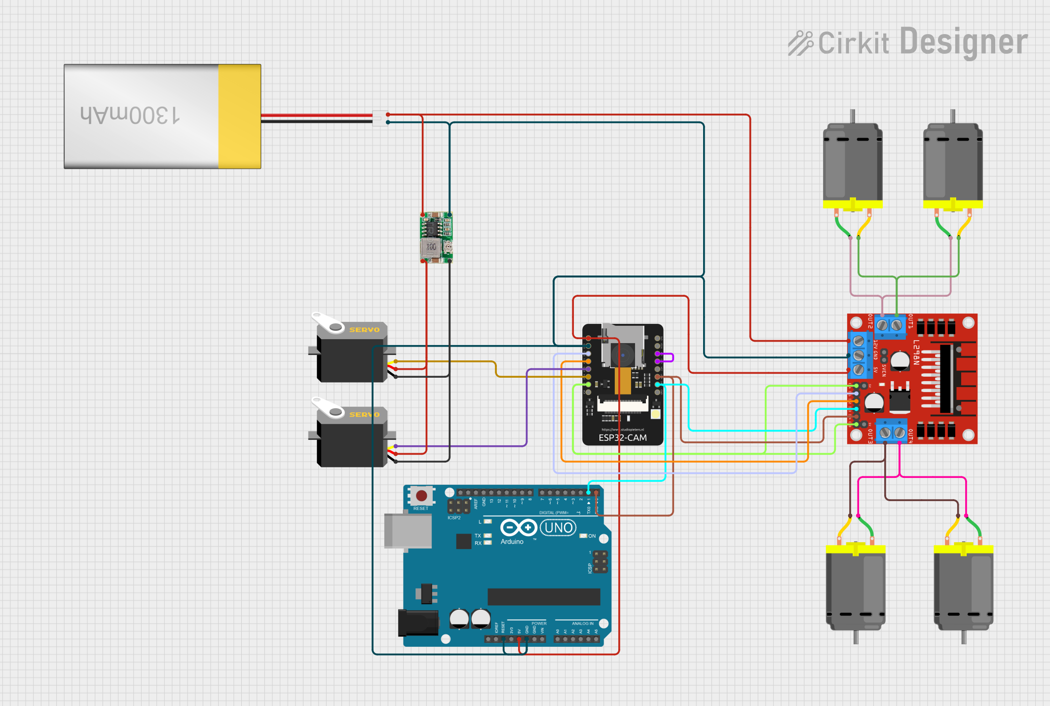
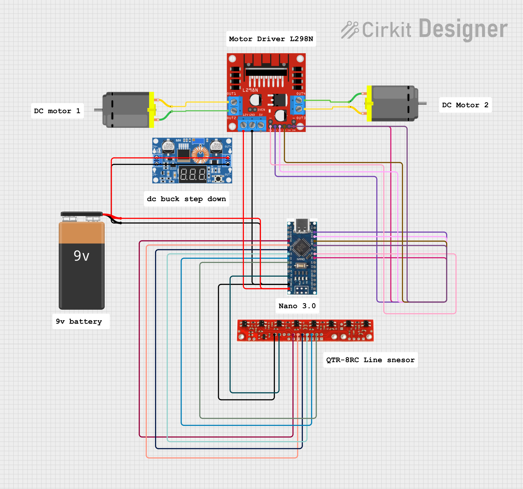

Explore Projects Built with L298N
Technical Specifications
- Operating Voltage: 5V to 46V
- Output Current: Up to 2A per channel (4A total with both channels)
- Logic Voltage: 5V
- Control Logic Levels: Low (0V) and High (5V)
- Power Dissipation: 25W (with proper heat sinking)
- Built-in Protection: Thermal shutdown and overcurrent protection
- Number of Channels: 2 (dual H-bridge)
- Motor Types Supported: DC motors and stepper motors
Pin Configuration and Descriptions
The L298N module typically includes the following pins and terminals:
| Pin/Terminal | Description |
|---|---|
| IN1 | Input pin to control the direction of Motor A (logic HIGH or LOW). |
| IN2 | Input pin to control the direction of Motor A (logic HIGH or LOW). |
| IN3 | Input pin to control the direction of Motor B (logic HIGH or LOW). |
| IN4 | Input pin to control the direction of Motor B (logic HIGH or LOW). |
| ENA | Enable pin for Motor A. PWM signal can be applied here to control speed. |
| ENB | Enable pin for Motor B. PWM signal can be applied here to control speed. |
| OUT1 | Output terminal connected to one lead of Motor A. |
| OUT2 | Output terminal connected to the other lead of Motor A. |
| OUT3 | Output terminal connected to one lead of Motor B. |
| OUT4 | Output terminal connected to the other lead of Motor B. |
| 12V | Power supply input for the motors (typically 7V to 12V). |
| 5V | Logic voltage input/output. Can be used to power the module or as a 5V output. |
| GND | Ground connection. |
Usage Instructions
How to Use the L298N in a Circuit
Power Connections:
- Connect the
12Vterminal to the motor power supply (e.g., 7V to 12V). - Connect the
GNDterminal to the ground of the power supply and the microcontroller. - If your microcontroller operates at 5V, you can use the
5Vpin as a logic power supply.
- Connect the
Motor Connections:
- Connect the motor leads to the
OUT1andOUT2terminals for Motor A, andOUT3andOUT4for Motor B.
- Connect the motor leads to the
Control Connections:
- Connect the
IN1,IN2,IN3, andIN4pins to the microcontroller's digital output pins. - Use the
ENAandENBpins to control the speed of Motor A and Motor B, respectively, by applying a PWM signal.
- Connect the
Direction Control:
- Set the
IN1andIN2pins to HIGH/LOW or LOW/HIGH to control the direction of Motor A. - Similarly, set the
IN3andIN4pins to HIGH/LOW or LOW/HIGH to control the direction of Motor B.
- Set the
Speed Control:
- Apply a PWM signal to the
ENApin to control the speed of Motor A. - Apply a PWM signal to the
ENBpin to control the speed of Motor B.
- Apply a PWM signal to the
Example Code for Arduino UNO
// Define motor control pins
const int IN1 = 7;  // Motor A direction control pin 1
const int IN2 = 6;  // Motor A direction control pin 2
const int ENA = 5;  // Motor A speed control (PWM)

// Setup function to initialize pins
void setup() {
  pinMode(IN1, OUTPUT);  // Set IN1 as output
  pinMode(IN2, OUTPUT);  // Set IN2 as output
  pinMode(ENA, OUTPUT);  // Set ENA as output
}

// Loop function to control motor
void loop() {
  // Rotate motor A forward at 50% speed
  digitalWrite(IN1, HIGH);  // Set IN1 HIGH
  digitalWrite(IN2, LOW);   // Set IN2 LOW
  analogWrite(ENA, 128);    // Set ENA to 50% duty cycle (128/255)

  delay(2000);  // Run motor for 2 seconds

  // Rotate motor A backward at 75% speed
  digitalWrite(IN1, LOW);   // Set IN1 LOW
  digitalWrite(IN2, HIGH);  // Set IN2 HIGH
  analogWrite(ENA, 192);    // Set ENA to 75% duty cycle (192/255)

  delay(2000);  // Run motor for 2 seconds

  // Stop motor A
  digitalWrite(IN1, LOW);   // Set IN1 LOW
  digitalWrite(IN2, LOW);   // Set IN2 LOW
  analogWrite(ENA, 0);      // Set ENA to 0% duty cycle (motor off)

  delay(2000);  // Wait for 2 seconds before repeating
}
Important Considerations and Best Practices
- Heat Dissipation: The L298N can get hot during operation. Use a heat sink or active cooling if driving motors at high currents.
- Power Supply: Ensure the motor power supply voltage matches the motor's specifications.
- Current Limits: Do not exceed the maximum current rating of 2A per channel to avoid damaging the module.
- Flyback Diodes: The L298N has built-in diodes for protection against back EMF, but additional external diodes may be used for added safety in high-power applications.
Troubleshooting and FAQs
Common Issues
Motors Not Running:
- Check all power connections and ensure the module is receiving the correct voltage.
- Verify that the
ENAandENBpins are enabled (HIGH or receiving a PWM signal).
Motor Running in the Wrong Direction:
- Swap the logic levels of the
IN1andIN2pins (orIN3andIN4for Motor B).
- Swap the logic levels of the
Overheating:
- Ensure proper heat dissipation using a heat sink or fan.
- Reduce the motor load or current if possible.
Noisy Operation:
- Add capacitors across the motor terminals to reduce electrical noise.
FAQs
Can the L298N drive stepper motors? Yes, the L298N can drive stepper motors by controlling the sequence of the
INpins. Use a stepper motor library for easier implementation.Can I use the L298N with a 3.3V microcontroller? The L298N is designed for 5V logic levels. Use a level shifter or ensure the control signals are compatible.
What is the maximum motor voltage supported? The L298N supports motor voltages up to 46V, but ensure your motor and power supply are compatible.