How to Use Actuator: Examples, Pinouts, and Specs
Introduction
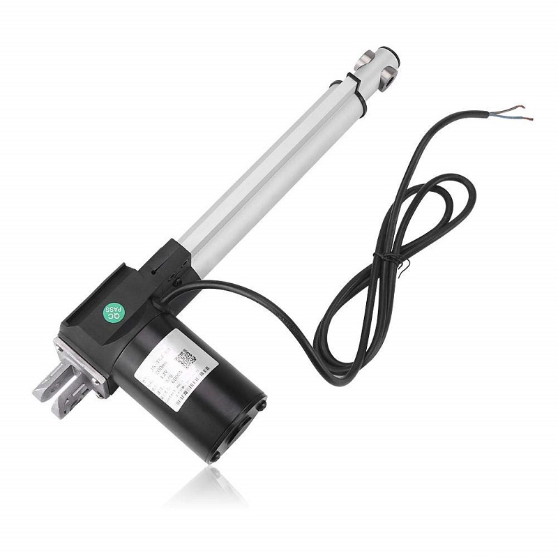
An actuator is a device that converts energy (typically electrical) into motion. It can be used in a variety of applications, including robotics, industrial machinery, and consumer electronics, to control a system or mechanism. Actuators are fundamental in creating physical movement in systems and are often used in conjunction with sensors and control systems to create a feedback loop.
Common applications of actuators include:
- Robotics arms
- Valve control
- Opening and closing vents
- Adjusting positions of camera systems
- Controlling various automotive components
Explore Projects Built with Actuator
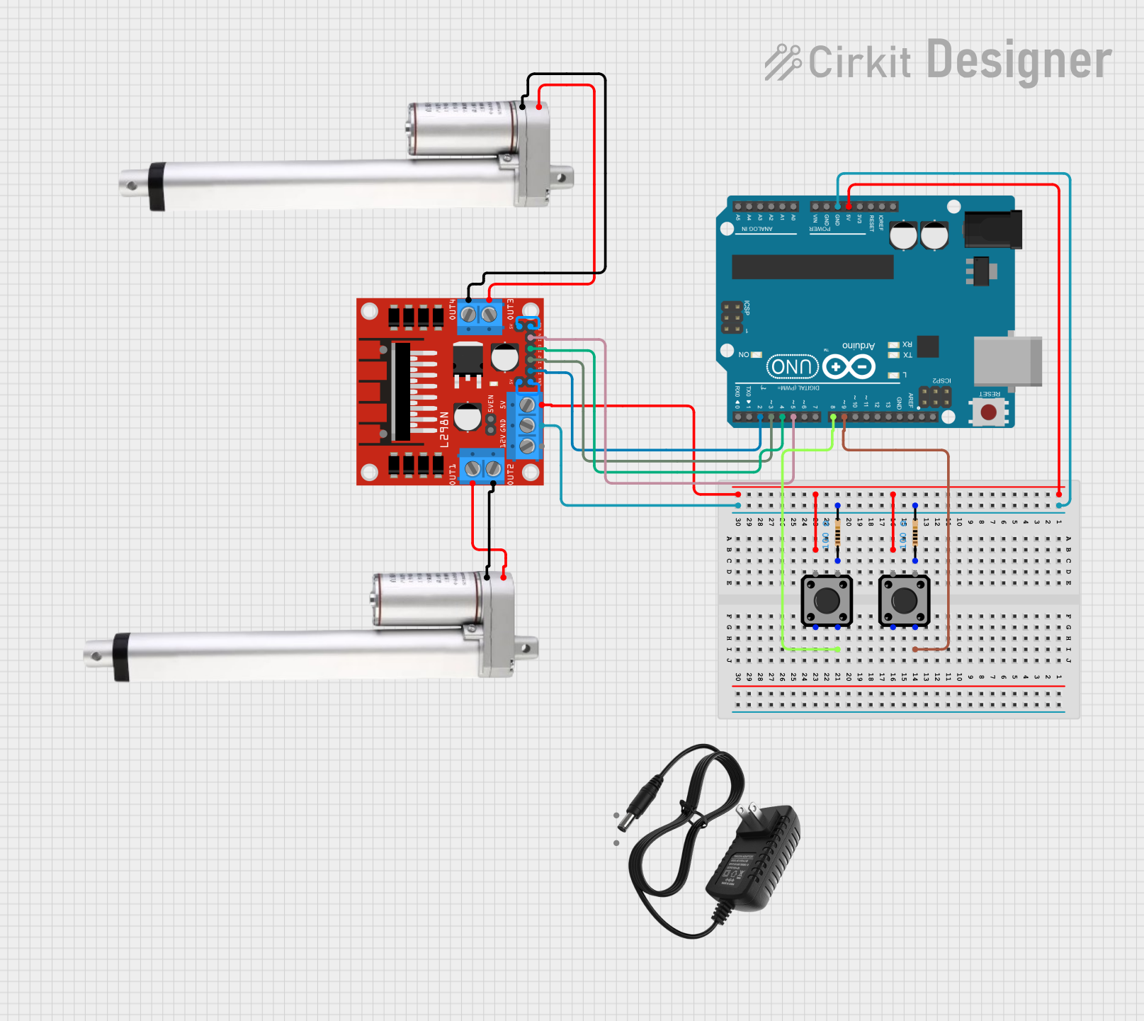
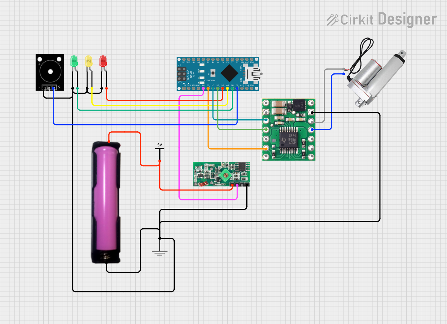

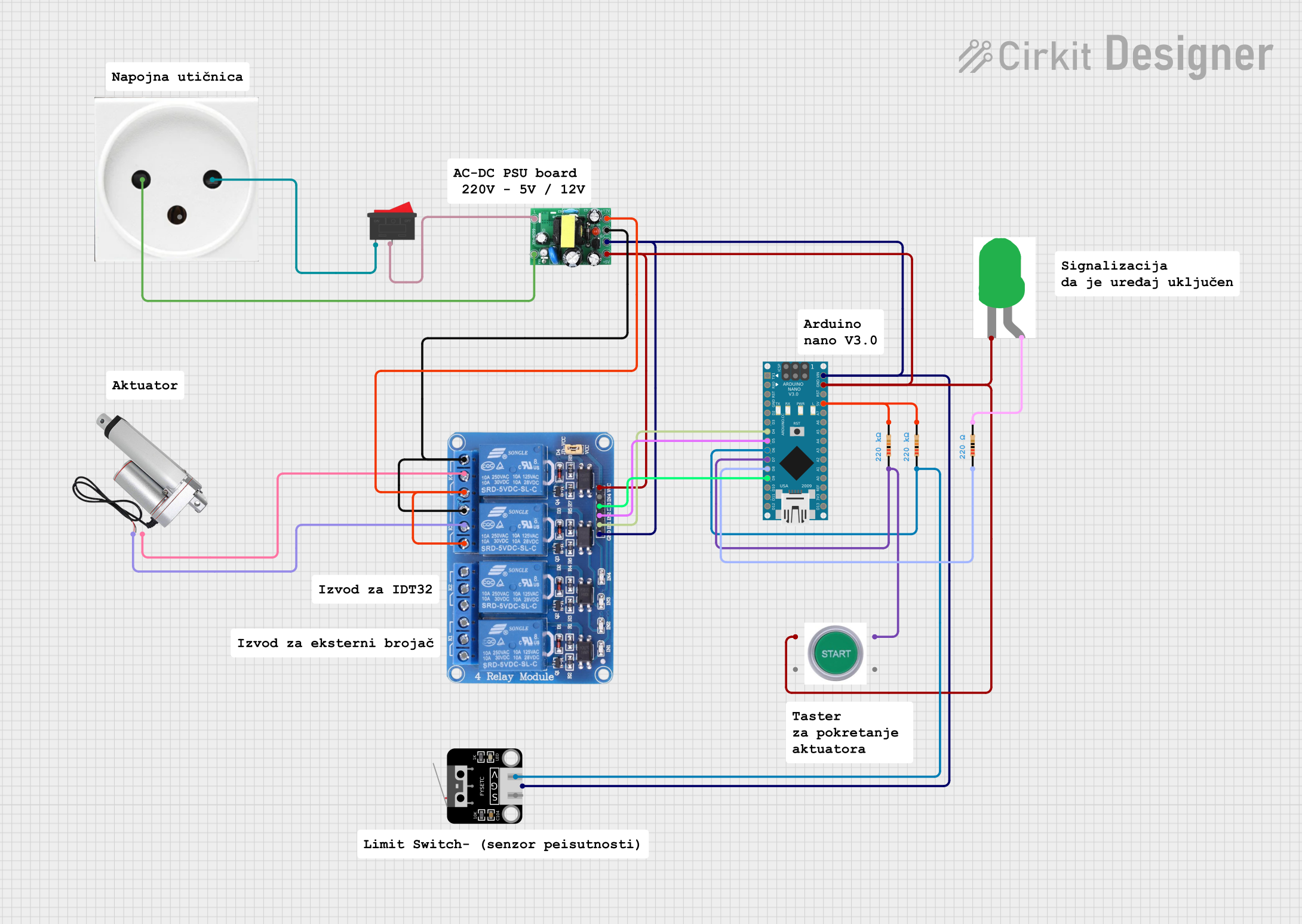
Explore Projects Built with Actuator
Technical Specifications
General Specifications
| Specification | Detail |
|---|---|
| Input Voltage | XX V |
| Maximum Current | XX A |
| Power Rating | XX W |
| Operating Temperature | -XX to XX°C |
| Control Signal | PWM/Analog Voltage/Digital (I2C/SPI) |
Pin Configuration
| Pin Number | Description |
|---|---|
| 1 | Power (+V) |
| 2 | Ground (GND) |
| 3 | Control Signal Input |
| 4 | Feedback Output (if applicable) |
Note: The actual pin configuration may vary depending on the type of actuator and manufacturer.
Usage Instructions
Integration into a Circuit
- Power Supply: Ensure that the power supply matches the voltage and current requirements of the actuator.
- Control Signal: Connect the control signal input to a PWM capable pin if the actuator is controlled by PWM, or to an analog output if it is controlled by varying voltage levels.
- Grounding: Connect the ground pin of the actuator to the common ground in the circuit.
- Feedback (Optional): If the actuator provides feedback, connect the feedback pin to an appropriate input on your microcontroller or control system.
Best Practices
- Use a flyback diode when switching inductive loads to prevent voltage spikes.
- Ensure that the actuator does not exceed its rated load to prevent damage.
- Implement current limiting to protect the actuator and control electronics.
- Use appropriate wire gauge for the current draw of the actuator.
Example Code for Arduino UNO
// Example code to control an actuator with Arduino UNO
#include <Servo.h>

Servo myActuator;  // create servo object to control an actuator

void setup() {
  myActuator.attach(9);  // attaches the actuator on pin 9 to the servo object
}

void loop() {
  myActuator.write(90);  // sets the actuator position according to the scaled value
  delay(1000);           // waits for the actuator to reach the position
  myActuator.write(0);   // sets the actuator back to the initial position
  delay(1000);           // waits for the actuator to reach the position
}
Note: The above code assumes the actuator is controlled like a servo motor. If your actuator requires a different control signal, adjust the code accordingly.
Troubleshooting and FAQs
Common Issues
- Actuator not moving: Check power supply and connections. Ensure the control signal is being sent correctly.
- Overheating: Reduce the load or duty cycle. Check for any obstructions or mechanical binding.
- Noisy operation: This could be due to mechanical issues. Inspect for wear and tear or loose parts.
FAQs
Q: Can I control the speed of the actuator? A: Yes, speed control is possible by varying the PWM signal or analog voltage, depending on the actuator's control interface.
Q: What should I do if the actuator is not responding to the control signal? A: Verify the control signal with an oscilloscope or logic analyzer. Check the wiring and ensure the signal is within the specified range for the actuator.
Q: How can I reverse the direction of the actuator? A: For actuators that allow for direction control, reversing the polarity of the control signal or using a H-bridge circuit can change the direction.
Remember, the exact troubleshooting steps may vary depending on the type of actuator and the application it is used in. Always refer to the manufacturer's datasheet for specific guidance.