How to Use RS485 to TTL by QQ: Examples, Pinouts, and Specs
Introduction
The RS485 to TTL converter by QQ is a versatile module designed to bridge communication between RS485 serial devices and TTL logic level devices. RS485 is a robust communication standard widely used for long-distance and noise-resistant data transmission, while TTL logic levels are commonly used in microcontrollers and other digital systems. This converter ensures seamless compatibility between these two standards, making it an essential component for industrial automation, IoT systems, and other serial communication applications.
Explore Projects Built with RS485 to TTL by QQ


Explore Projects Built with RS485 to TTL by QQ
Common Applications and Use Cases
- Industrial automation and control systems
- Long-distance communication between microcontrollers
- IoT devices requiring RS485 communication
- Data acquisition systems
- Home automation networks
Technical Specifications
Key Technical Details
- Input Voltage: 3.3V to 5V DC
- Communication Protocol: RS485 to TTL
- Baud Rate: Up to 115200 bps
- Operating Temperature: -40°C to 85°C
- Maximum Communication Distance: Up to 1200 meters (with proper cabling)
- Driver IC: Typically based on MAX485 or equivalent
- Dimensions: Compact PCB module (varies by manufacturer)
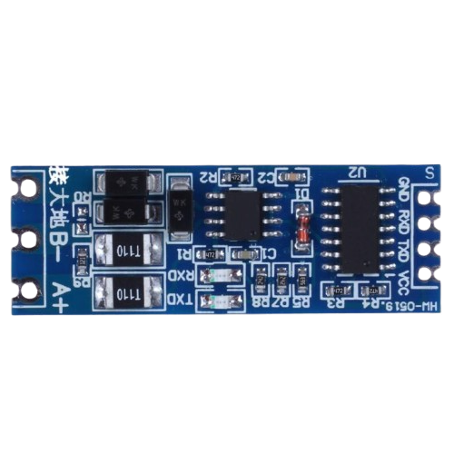
Pin Configuration and Descriptions
The RS485 to TTL module typically has the following pinout:
| Pin Name | Type | Description |
|---|---|---|
| VCC | Power Input | Connect to 3.3V or 5V DC power supply. |
| GND | Ground | Connect to the ground of the power supply. |
| RO | Output | Receiver Output: TTL-level data received from the RS485 bus. |
| DI | Input | Driver Input: TTL-level data to be transmitted over the RS485 bus. |
| DE | Input | Driver Enable: High to enable transmission mode, low to disable. |
| RE | Input | Receiver Enable: Low to enable receiving mode, high to disable. |
| A (RS485+) | RS485 Signal | Non-inverting RS485 signal line. |
| B (RS485-) | RS485 Signal | Inverting RS485 signal line. |
Note: Some modules may combine DE and RE into a single pin for simplified control.
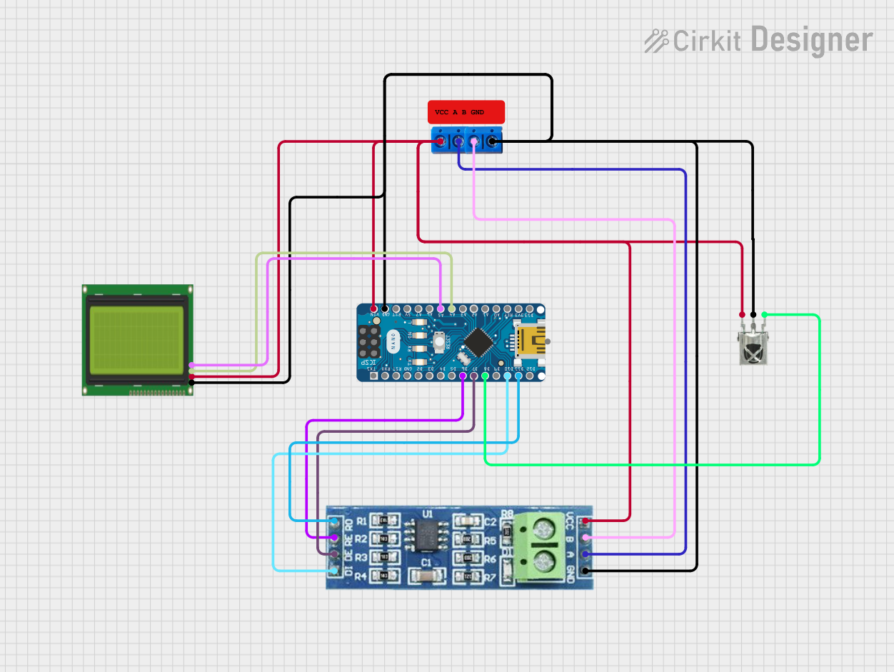
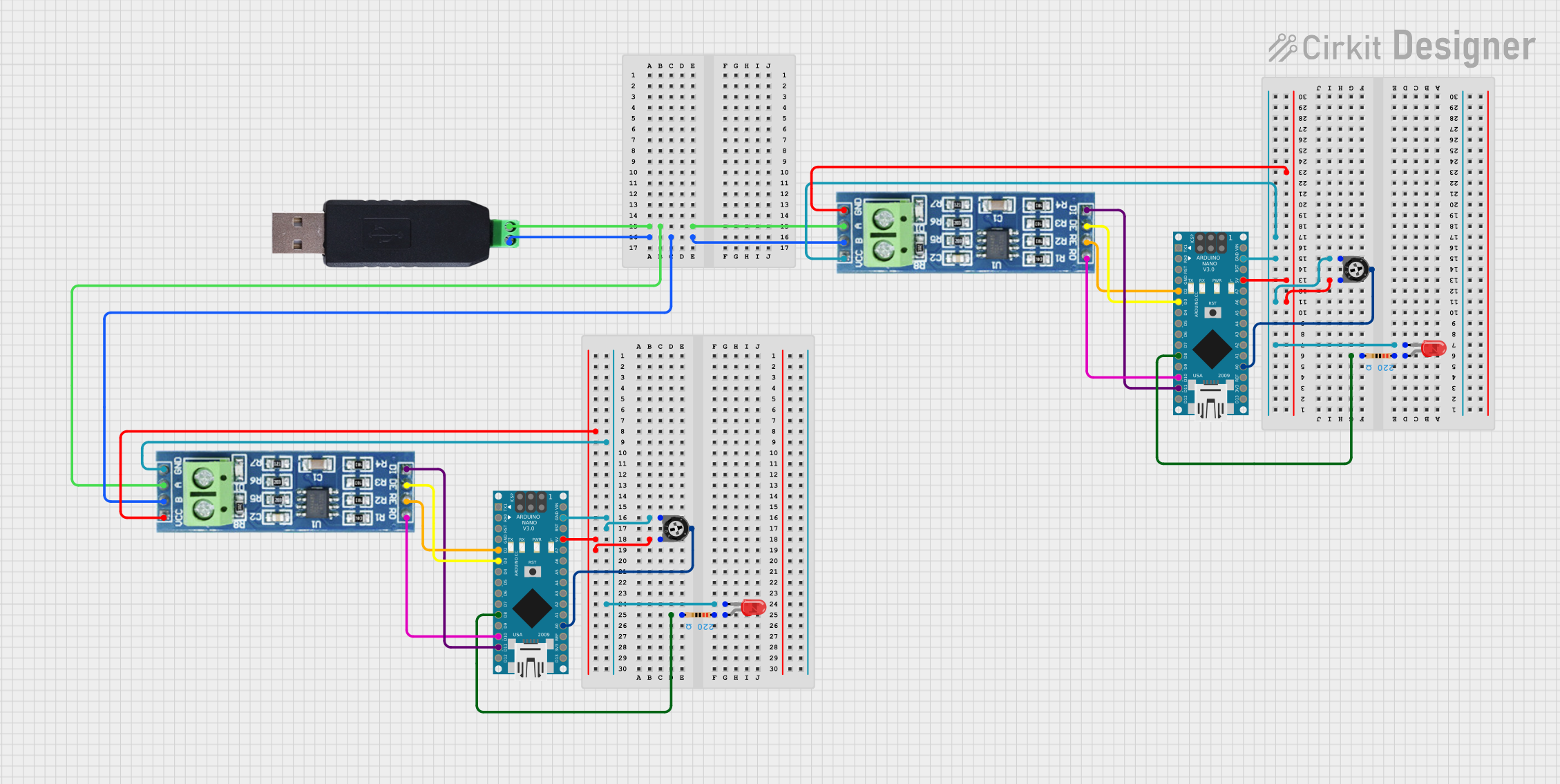
Usage Instructions
How to Use the Component in a Circuit
- Power the Module: Connect the VCC pin to a 3.3V or 5V power source and the GND pin to the ground.
- Connect RS485 Lines: Attach the A (RS485+) and B (RS485-) pins to the RS485 bus. Ensure proper polarity.
- Connect TTL Lines:
- Connect the RO pin to the RX pin of your microcontroller (for receiving data).
- Connect the DI pin to the TX pin of your microcontroller (for transmitting data).
- Control DE and RE:
- For modules with separate DE and RE pins:
- Set DE high to enable transmission and low to disable it.
- Set RE low to enable receiving and high to disable it.
- For modules with combined DE/RE pins, toggle the pin high for transmission and low for receiving.
- For modules with separate DE and RE pins:
- Configure Communication: Set the baud rate and other serial communication parameters in your microcontroller code to match the RS485 device.
Important Considerations and Best Practices
- Use twisted-pair cables for RS485 connections to minimize noise and signal degradation.
- Terminate the RS485 bus with 120-ohm resistors at both ends to prevent signal reflections.
- Ensure that all devices on the RS485 bus share a common ground.
- Avoid exceeding the maximum communication distance or baud rate for reliable operation.
Example Code for Arduino UNO
Below is an example of how to use the RS485 to TTL module with an Arduino UNO:
// Include the SoftwareSerial library for serial communication
#include <SoftwareSerial.h>

// Define RS485 pins
#define RS485_RX 10  // RO pin connected to Arduino pin 10
#define RS485_TX 11  // DI pin connected to Arduino pin 11
#define RS485_DE 8   // DE pin connected to Arduino pin 8
#define RS485_RE 9   // RE pin connected to Arduino pin 9

// Create a SoftwareSerial object
SoftwareSerial RS485Serial(RS485_RX, RS485_TX);

void setup() {
  // Initialize serial communication
  Serial.begin(9600);          // For debugging via Serial Monitor
  RS485Serial.begin(9600);     // RS485 communication baud rate

  // Set DE and RE pins as outputs
  pinMode(RS485_DE, OUTPUT);
  pinMode(RS485_RE, OUTPUT);

  // Set module to receive mode by default
  digitalWrite(RS485_DE, LOW);
  digitalWrite(RS485_RE, LOW);

  Serial.println("RS485 to TTL Module Initialized");
}

void loop() {
  // Example: Send data over RS485
  digitalWrite(RS485_DE, HIGH);  // Enable transmission
  digitalWrite(RS485_RE, HIGH);  // Disable receiving
  RS485Serial.println("Hello RS485!");  // Send data
  delay(100);  // Short delay
  digitalWrite(RS485_DE, LOW);   // Disable transmission
  digitalWrite(RS485_RE, LOW);   // Enable receiving

  // Example: Receive data from RS485
  if (RS485Serial.available()) {
    String receivedData = RS485Serial.readString();
    Serial.print("Received: ");
    Serial.println(receivedData);  // Print received data to Serial Monitor
  }

  delay(1000);  // Wait before next iteration
}
Note: Adjust the baud rate and pin numbers as needed for your specific setup.
Troubleshooting and FAQs
Common Issues and Solutions
No Data Transmission or Reception:
- Verify that the DE and RE pins are correctly toggled for transmission and reception.
- Check the wiring of the RS485 A and B lines. Ensure proper polarity.
- Confirm that the baud rate matches between the RS485 device and the microcontroller.
Data Corruption or Noise:
- Use shielded or twisted-pair cables for RS485 connections.
- Add 120-ohm termination resistors at both ends of the RS485 bus.
Module Not Powering On:
- Ensure the VCC and GND pins are properly connected to a 3.3V or 5V power source.
- Check for loose or faulty connections.
Communication Distance Issues:
- Ensure the total cable length does not exceed 1200 meters.
- Reduce the baud rate for longer distances to improve reliability.
FAQs
Q: Can I use this module with a 3.3V microcontroller?
A: Yes, the module supports both 3.3V and 5V logic levels. Ensure the VCC pin is connected to the appropriate voltage.
Q: How many devices can I connect to the RS485 bus?
A: RS485 supports up to 32 devices on a single bus. Use repeaters for larger networks.
Q: Do I need to manually toggle DE and RE for every transmission?
A: Yes, unless your module combines DE and RE into a single pin, you must toggle them manually in your code.
Q: Can I use this module for half-duplex communication?
A: Yes, RS485 is inherently a half-duplex protocol, and this module supports it.
By following this documentation, you can effectively integrate the RS485 to TTL converter by QQ into your projects for reliable and long-distance serial communication.