
How to Use V_REG_MIC5216: Examples, Pinouts, and Specs
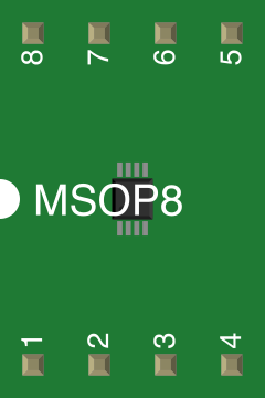
 Design with V_REG_MIC5216 in Cirkit Designer
Introduction
The MIC5216 is a low-dropout voltage regulator (LDO) designed to provide a stable and accurate output voltage with low noise. It is particularly well-suited for battery-powered devices due to its low quiescent current and high efficiency. The MIC5216 includes advanced features such as thermal shutdown and current limiting, ensuring reliable operation under various conditions. Its compact design and high performance make it ideal for portable electronics, wireless devices, and other applications requiring efficient voltage regulation.
Explore Projects Built with V_REG_MIC5216
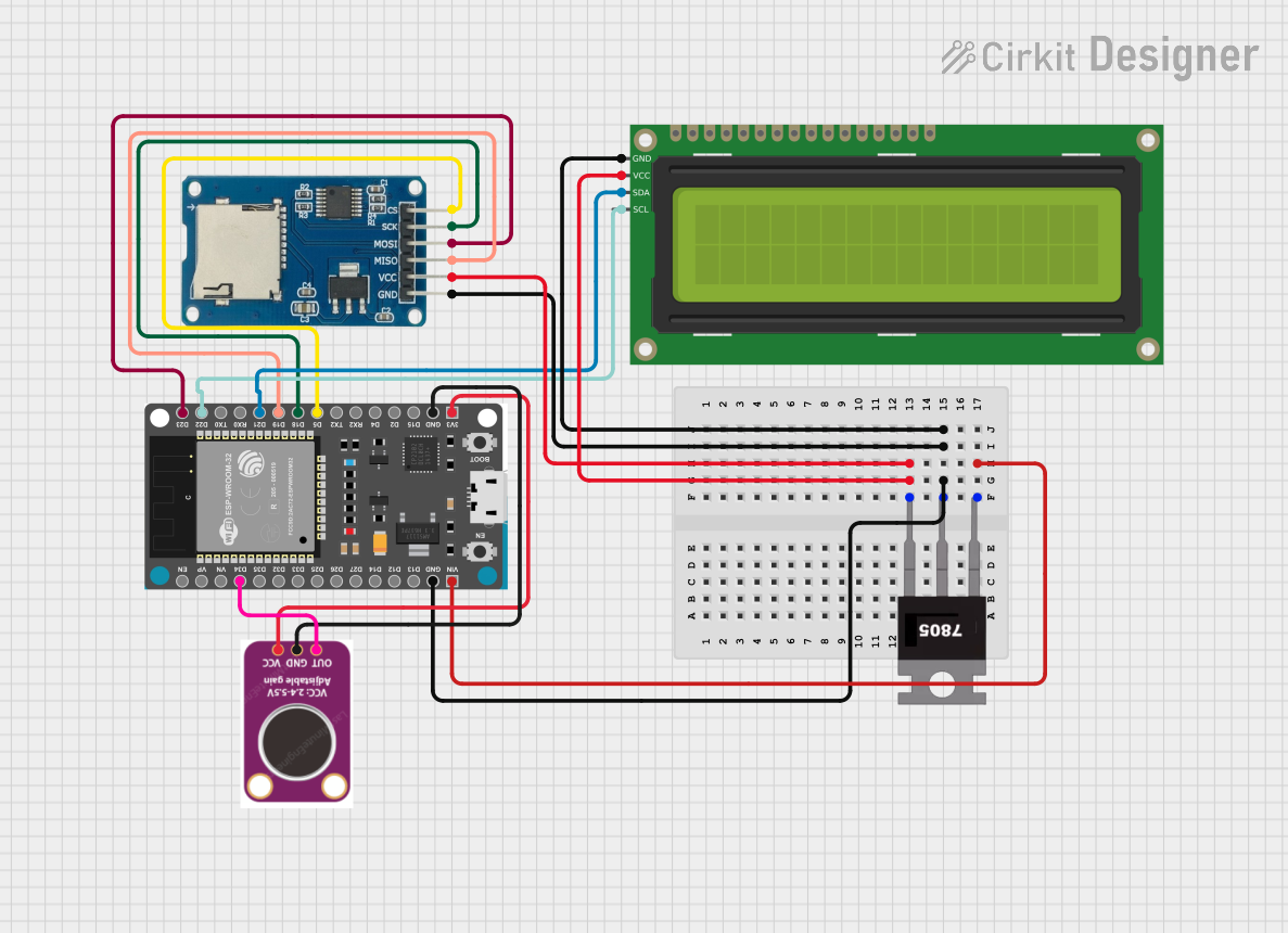 Open Project in Cirkit Designer
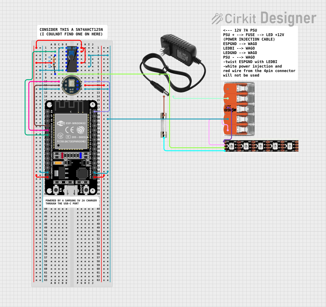 Open Project in Cirkit Designer
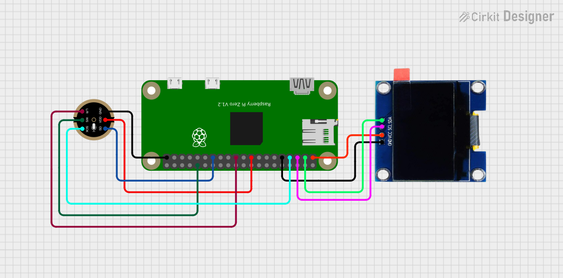 Open Project in Cirkit Designer
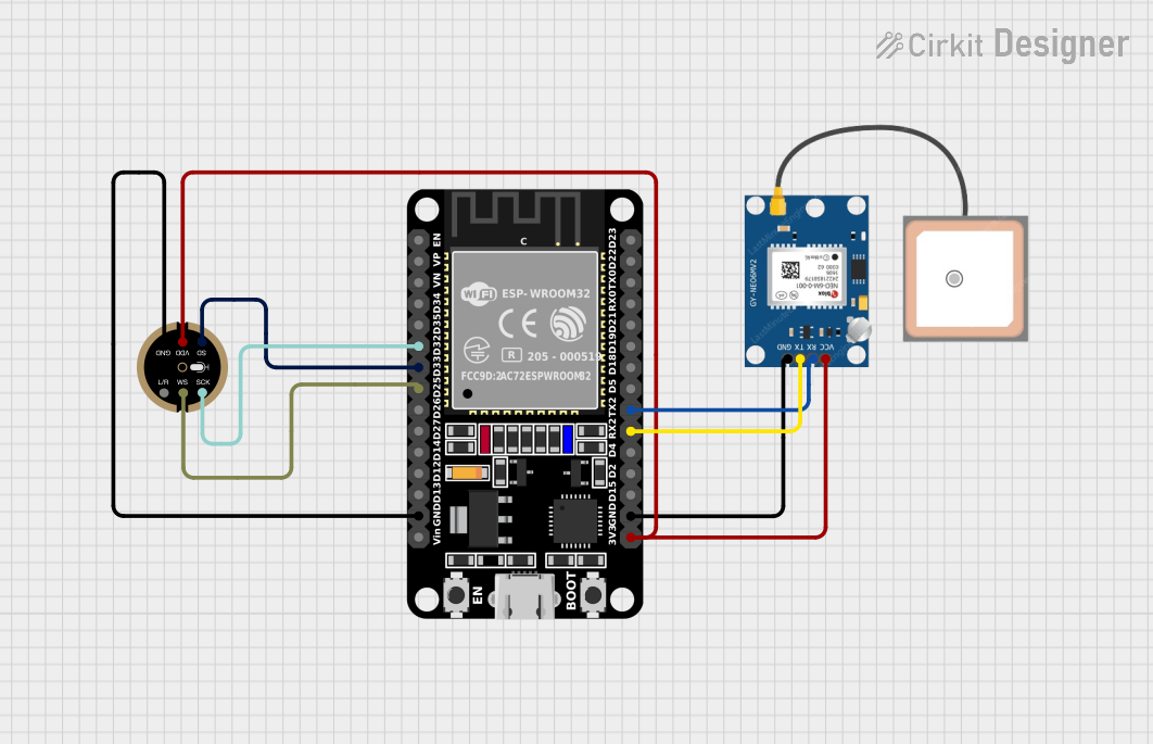 Open Project in Cirkit Designer
Explore Projects Built with V_REG_MIC5216
Open Project in Cirkit DesignerOpen Project in Cirkit DesignerOpen Project in Cirkit DesignerOpen Project in Cirkit DesignerCommon Applications
- Battery-powered devices (e.g., smartphones, wearables)
- Portable electronics
- Wireless communication modules
- Low-noise analog circuits
- Microcontroller-based systems
Technical Specifications
Key Specifications
| Parameter | Value |
|---|---|
| Input Voltage Range | 2.5V to 12V |
| Output Voltage Range | 1.25V to 5.5V (fixed or adjustable) |
| Output Current | Up to 150mA |
| Dropout Voltage | 85mV at 50mA, 165mV at 150mA |
| Quiescent Current | 29µA (typical) |
| Output Voltage Accuracy | ±1% |
| Noise | 30µVRMS (10Hz to 100kHz) |
| Operating Temperature Range | -40°C to +125°C |
| Protection Features | Thermal shutdown, current limiting |
Pin Configuration and Descriptions
The MIC5216 is available in several package types, such as SOT-23-5 and TSOT-23-5. Below is the pin configuration for the SOT-23-5 package:
| Pin Number | Pin Name | Description |
|---|---|---|
| 1 | VIN | Input voltage. Connect to the power source. |
| 2 | GND | Ground. Connect to the system ground. |
| 3 | EN | Enable pin. Drive high to enable the regulator; drive low to disable it. |
| 4 | BYP | Bypass pin. Connect a capacitor (e.g., 470pF) to reduce output noise. |
| 5 | VOUT | Regulated output voltage. Connect to the load. |
Usage Instructions
How to Use the MIC5216 in a Circuit
- Power Supply: Connect the input voltage (VIN) to a power source within the specified range (2.5V to 12V).
- Output Capacitor: Place a low-ESR capacitor (e.g., 1µF ceramic) between VOUT and GND to ensure stability.
- Bypass Capacitor: For low-noise applications, connect a 470pF capacitor between BYP and GND.
- Enable Pin: Drive the EN pin high (logic level) to enable the regulator. If unused, connect it to VIN.
- Ground Connection: Ensure a solid ground connection for proper operation.
Important Considerations
- Thermal Management: Ensure adequate heat dissipation, especially when operating at high currents or input voltages.
- Input Capacitor: Use a 1µF capacitor close to the VIN pin to improve transient response and stability.
- Load Current: Do not exceed the maximum output current of 150mA to avoid triggering current limiting.
- PCB Layout: Minimize trace lengths for VIN, VOUT, and GND to reduce noise and improve performance.
Example: Using MIC5216 with Arduino UNO
The MIC5216 can be used to power an Arduino UNO or other microcontroller-based systems. Below is an example circuit and Arduino code to enable the regulator:
Circuit Diagram
- Connect VIN to a 9V battery or other suitable power source.
- Connect VOUT to the Arduino UNO's 5V pin.
- Connect GND to the Arduino's GND pin.
- Use a 470pF capacitor on the BYP pin for noise reduction.
Arduino Code
// Example code to control the MIC5216's enable pin using Arduino UNO

const int enablePin = 7; // Pin connected to the MIC5216 EN pin

void setup() {
  pinMode(enablePin, OUTPUT); // Set the enable pin as an output
  digitalWrite(enablePin, HIGH); // Enable the MIC5216 regulator
}

void loop() {
  // The MIC5216 remains enabled, providing a stable output voltage
  delay(1000); // Placeholder for other tasks
}
Troubleshooting and FAQs
Common Issues and Solutions
| Issue | Possible Cause | Solution |
|---|---|---|
| No output voltage | EN pin not driven high | Ensure the EN pin is connected to a logic high or VIN. |
| Output voltage is unstable | Insufficient output capacitor | Use a low-ESR capacitor (e.g., 1µF ceramic) on VOUT. |
| Excessive noise on output | Bypass capacitor not connected | Add a 470pF capacitor between BYP and GND. |
| Regulator overheating | High input voltage or load current | Improve heat dissipation or reduce load current. |
| Output voltage lower than expected | Incorrect resistor values (adjustable version) | Verify resistor divider values for the desired output voltage. |
FAQs
Can the MIC5216 operate without a bypass capacitor?
Yes, but the output noise will be higher. For low-noise applications, a 470pF capacitor is recommended.What happens if the input voltage drops below the output voltage?
The MIC5216 will enter dropout mode, and the output voltage will track the input voltage minus the dropout voltage.Is the MIC5216 suitable for powering sensitive analog circuits?
Yes, its low noise and high accuracy make it ideal for sensitive analog applications.Can I leave the EN pin floating?
No, the EN pin must be connected to either VIN (to enable) or GND (to disable).
By following this documentation, users can effectively integrate the MIC5216 into their designs for reliable and efficient voltage regulation.