How to Use DC-DC 12V 5V 3.3V: Examples, Pinouts, and Specs
Introduction
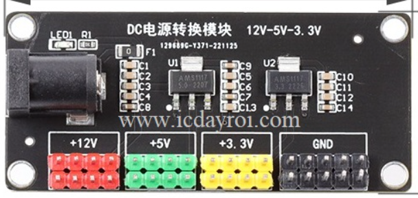
The DC-DC 12V 5V 3.3V converter, manufactured by ESP32 (Part ID: 477215632t31), is a versatile and efficient power management component. It is designed to step down or step up input voltage levels to provide stable output voltages of 12V, 5V, and 3.3V. This makes it an essential component for powering a wide range of electronic devices and circuits.
Explore Projects Built with DC-DC 12V 5V 3.3V


Explore Projects Built with DC-DC 12V 5V 3.3V
Common Applications and Use Cases
- Powering microcontrollers (e.g., ESP32, Arduino, Raspberry Pi)
- Supplying stable voltage to sensors, actuators, and modules
- Battery-powered systems requiring multiple voltage levels
- Robotics and IoT devices
- Portable electronics and embedded systems
Technical Specifications
Key Technical Details
| Parameter | Value |
|---|---|
| Input Voltage Range | 6V to 24V |
| Output Voltages | 12V, 5V, 3.3V |
| Output Current (Max) | 2A (12V), 3A (5V), 3A (3.3V) |
| Efficiency | Up to 95% |
| Switching Frequency | 150 kHz |
| Operating Temperature | -40°C to +85°C |
| Dimensions | 45mm x 25mm x 15mm |
Pin Configuration and Descriptions
| Pin Name | Pin Type | Description |
|---|---|---|
| VIN | Power Input | Connect to the input voltage source (6V to 24V). |
| GND | Ground | Common ground for input and output. |
| VOUT_12V | Power Output | Provides a stable 12V output. |
| VOUT_5V | Power Output | Provides a stable 5V output. |
| VOUT_3.3V | Power Output | Provides a stable 3.3V output. |
| EN | Enable Input | Active-high pin to enable the converter. |
Usage Instructions
How to Use the Component in a Circuit
Connect the Input Voltage:
- Attach the input voltage source (6V to 24V) to the
VINpin. - Connect the ground of the input source to the
GNDpin.
- Attach the input voltage source (6V to 24V) to the
Select the Desired Output Voltage:
- Use the
VOUT_12V,VOUT_5V, orVOUT_3.3Vpins to power your devices. - Ensure the connected load does not exceed the maximum current rating for each output.
- Use the
Enable the Converter:
- To activate the converter, apply a high signal (e.g., 3.3V or 5V) to the
ENpin. - If the
ENpin is left floating or connected to ground, the converter will remain disabled.
- To activate the converter, apply a high signal (e.g., 3.3V or 5V) to the
Connect the Load:
- Attach your devices or circuits to the appropriate output voltage pin(s).
- Ensure proper grounding by connecting the load's ground to the
GNDpin.
Important Considerations and Best Practices
- Input Voltage Range: Ensure the input voltage is within the specified range (6V to 24V). Exceeding this range may damage the converter.
- Heat Dissipation: For high current loads, consider adding a heatsink or ensuring adequate ventilation to prevent overheating.
- Decoupling Capacitors: Add decoupling capacitors (e.g., 10µF and 0.1µF) near the output pins to reduce noise and improve stability.
- Enable Pin Usage: If the
ENpin is not used, connect it toVINto keep the converter enabled by default.
Example: Using with Arduino UNO
Below is an example of how to use the DC-DC converter to power an Arduino UNO with 5V output:
Circuit Connections
- Connect a 12V battery to the
VINandGNDpins of the converter. - Connect the
VOUT_5Vpin to the Arduino's5Vpin. - Connect the converter's
GNDpin to the Arduino'sGNDpin.
Arduino Code Example
// Example code to blink an LED using Arduino UNO powered by the DC-DC converter

const int ledPin = 13; // Pin connected to the onboard LED

void setup() {
  pinMode(ledPin, OUTPUT); // Set the LED pin as an output
}

void loop() {
  digitalWrite(ledPin, HIGH); // Turn the LED on
  delay(1000);                // Wait for 1 second
  digitalWrite(ledPin, LOW);  // Turn the LED off
  delay(1000);                // Wait for 1 second
}
Troubleshooting and FAQs
Common Issues and Solutions
| Issue | Possible Cause | Solution |
|---|---|---|
| No output voltage | Input voltage is not connected properly | Verify the input voltage and connections. |
| Output voltage is unstable | Insufficient decoupling capacitors | Add capacitors near the output pins. |
| Converter overheats | Load exceeds maximum current rating | Reduce the load or improve cooling. |
| Converter does not turn on | EN pin is not connected or is low |
Connect EN pin to VIN or a high signal. |
FAQs
Can I use this converter with a 24V input?
- Yes, the converter supports input voltages up to 24V.
What happens if I connect a load that exceeds the current rating?
- The converter may overheat or shut down to protect itself. Always ensure the load is within the specified limits.
Is it safe to use all three output voltages simultaneously?
- Yes, as long as the total current draw does not exceed the converter's capacity.
Can I use this converter with a lithium-ion battery?
- Yes, it is compatible with lithium-ion batteries, provided the battery voltage is within the input range.
By following this documentation, you can effectively integrate the DC-DC 12V 5V 3.3V converter into your projects and ensure reliable performance.