
How to Use ATH20 Temperature & Humidity: Examples, Pinouts, and Specs
 Design with ATH20 Temperature & Humidity in Cirkit Designer
Introduction
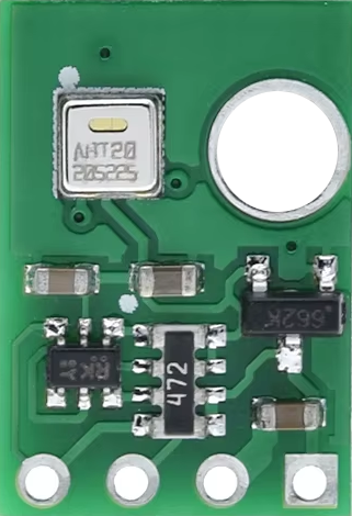
The ATH20 is a digital sensor that measures both temperature and humidity, providing accurate readings for environmental monitoring and control applications. It is designed for ease of use, featuring a digital output that simplifies integration into microcontroller-based systems. The ATH20 is widely used in applications such as weather stations, HVAC systems, industrial automation, and IoT devices.
Explore Projects Built with ATH20 Temperature & Humidity
 Open Project in Cirkit Designer
 Open Project in Cirkit Designer
 Open Project in Cirkit Designer
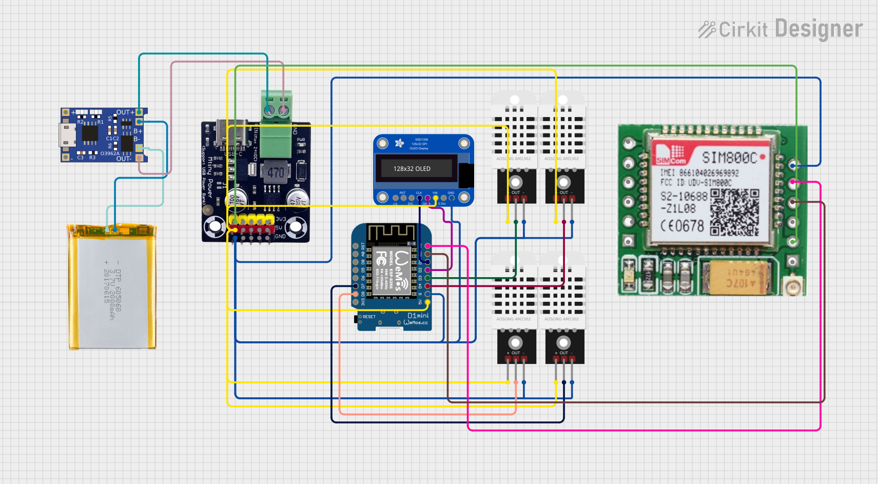 Open Project in Cirkit Designer
Explore Projects Built with ATH20 Temperature & Humidity
Open Project in Cirkit DesignerOpen Project in Cirkit DesignerOpen Project in Cirkit DesignerOpen Project in Cirkit DesignerTechnical Specifications
- Temperature Range: -40°C to 80°C
- Humidity Range: 0% to 100% RH (Relative Humidity)
- Temperature Accuracy: ±0.3°C
- Humidity Accuracy: ±2% RH
- Operating Voltage: 3.3V to 5.5V
- Communication Protocol: I²C
- Power Consumption: <1 mA during measurement
- Response Time: <2 seconds
- Dimensions: 15mm x 10mm x 5mm
Pin Configuration and Descriptions
The ATH20 sensor has four pins, as described in the table below:
| Pin Number | Pin Name | Description |
|---|---|---|
| 1 | VCC | Power supply input (3.3V to 5.5V) |
| 2 | GND | Ground connection |
| 3 | SDA | Serial Data Line for I²C communication |
| 4 | SCL | Serial Clock Line for I²C communication |
Usage Instructions
How to Use the ATH20 in a Circuit
- Power Supply: Connect the VCC pin to a 3.3V or 5V power source and the GND pin to the ground of your circuit.
- I²C Communication: Connect the SDA and SCL pins to the corresponding I²C pins on your microcontroller. Use pull-up resistors (typically 4.7kΩ) on both SDA and SCL lines if not already present on your board.
- Initialization: Configure your microcontroller to communicate with the ATH20 using the I²C protocol. The default I²C address of the ATH20 is
0x38. - Data Reading: Send a command to the sensor to initiate a measurement, then read the temperature and humidity data from the sensor's registers.
Important Considerations and Best Practices
- Ensure the sensor is not exposed to direct sunlight or water droplets, as these can affect accuracy.
- Avoid placing the sensor near heat sources or in areas with high airflow, as this may cause inaccurate readings.
- Allow the sensor to stabilize for a few seconds after powering it on before taking measurements.
- Use decoupling capacitors (e.g., 0.1µF) near the VCC pin to reduce noise in the power supply.
Example Code for Arduino UNO
Below is an example of how to use the ATH20 sensor with an Arduino UNO:
#include <Wire.h>

// ATH20 I²C address
#define ATH20_ADDRESS 0x38

void setup() {
  Wire.begin(); // Initialize I²C communication
  Serial.begin(9600); // Start serial communication for debugging

  // Initialize the sensor
  if (!initializeATH20()) {
    Serial.println("ATH20 initialization failed!");
    while (1); // Halt execution if initialization fails
  }
  Serial.println("ATH20 initialized successfully.");
}

void loop() {
  float temperature, humidity;

  // Read temperature and humidity
  if (readATH20(&temperature, &humidity)) {
    Serial.print("Temperature: ");
    Serial.print(temperature);
    Serial.println(" °C");

    Serial.print("Humidity: ");
    Serial.print(humidity);
    Serial.println(" %");
  } else {
    Serial.println("Failed to read from ATH20.");
  }

  delay(2000); // Wait 2 seconds before the next reading
}

bool initializeATH20() {
  Wire.beginTransmission(ATH20_ADDRESS);
  if (Wire.endTransmission() != 0) {
    return false; // Sensor not found
  }
  return true;
}

bool readATH20(float *temperature, float *humidity) {
  Wire.beginTransmission(ATH20_ADDRESS);
  Wire.write(0xAC); // Command to start measurement
  Wire.endTransmission();
  delay(80); // Wait for measurement to complete

  Wire.requestFrom(ATH20_ADDRESS, 6); // Request 6 bytes of data
  if (Wire.available() != 6) {
    return false; // Data not available
  }

  uint8_t data[6];
  for (int i = 0; i < 6; i++) {
    data[i] = Wire.read();
  }

  // Convert data to temperature and humidity
  uint16_t rawHumidity = (data[1] << 8) | data[2];
  uint16_t rawTemperature = (data[3] << 8) | data[4];

  *humidity = (rawHumidity * 100.0) / 65536.0;
  *temperature = ((rawTemperature * 200.0) / 65536.0) - 50.0;

  return true;
}
Troubleshooting and FAQs
Common Issues
No Data from Sensor:
- Ensure the sensor is powered correctly (check VCC and GND connections).
- Verify the I²C address (
0x38) matches the one used in your code. - Check for proper pull-up resistors on the SDA and SCL lines.
Inaccurate Readings:
- Ensure the sensor is not exposed to extreme environmental conditions (e.g., direct sunlight, water).
- Allow the sensor to stabilize after powering it on.
I²C Communication Errors:
- Check the wiring between the sensor and the microcontroller.
- Ensure the I²C clock speed is compatible with the sensor (typically 100kHz or 400kHz).
FAQs
Q: Can the ATH20 operate at 3.3V?
A: Yes, the ATH20 supports an operating voltage range of 3.3V to 5.5V.
Q: Do I need external pull-up resistors for I²C communication?
A: Yes, if your microcontroller or breakout board does not have built-in pull-up resistors, you need to add 4.7kΩ resistors on the SDA and SCL lines.
Q: How often can I take measurements?
A: The sensor has a response time of less than 2 seconds, so you can take measurements approximately every 2 seconds.
Q: Can the ATH20 be used outdoors?
A: While the ATH20 can be used outdoors, it should be protected from direct sunlight, rain, and extreme conditions to ensure accurate readings and longevity.