How to Use Arduino MKR WiFi 1010: Examples, Pinouts, and Specs
 Design with Arduino MKR WiFi 1010 in Cirkit Designer
Introduction
The Arduino MKR WiFi 1010 is a versatile and powerful Internet of Things (IoT) development board that integrates the functionality of the Arduino Zero with robust Wi-Fi connectivity. It is designed around the Microchip SAMD21 microcontroller and the u-blox NINA-W10 series low power 2.4GHz IEEE® 802.11 b/g/n Wi-Fi module. This board is perfect for IoT projects, wireless communication applications, and for those looking to step into the world of connected devices with ease.
Explore Projects Built with Arduino MKR WiFi 1010

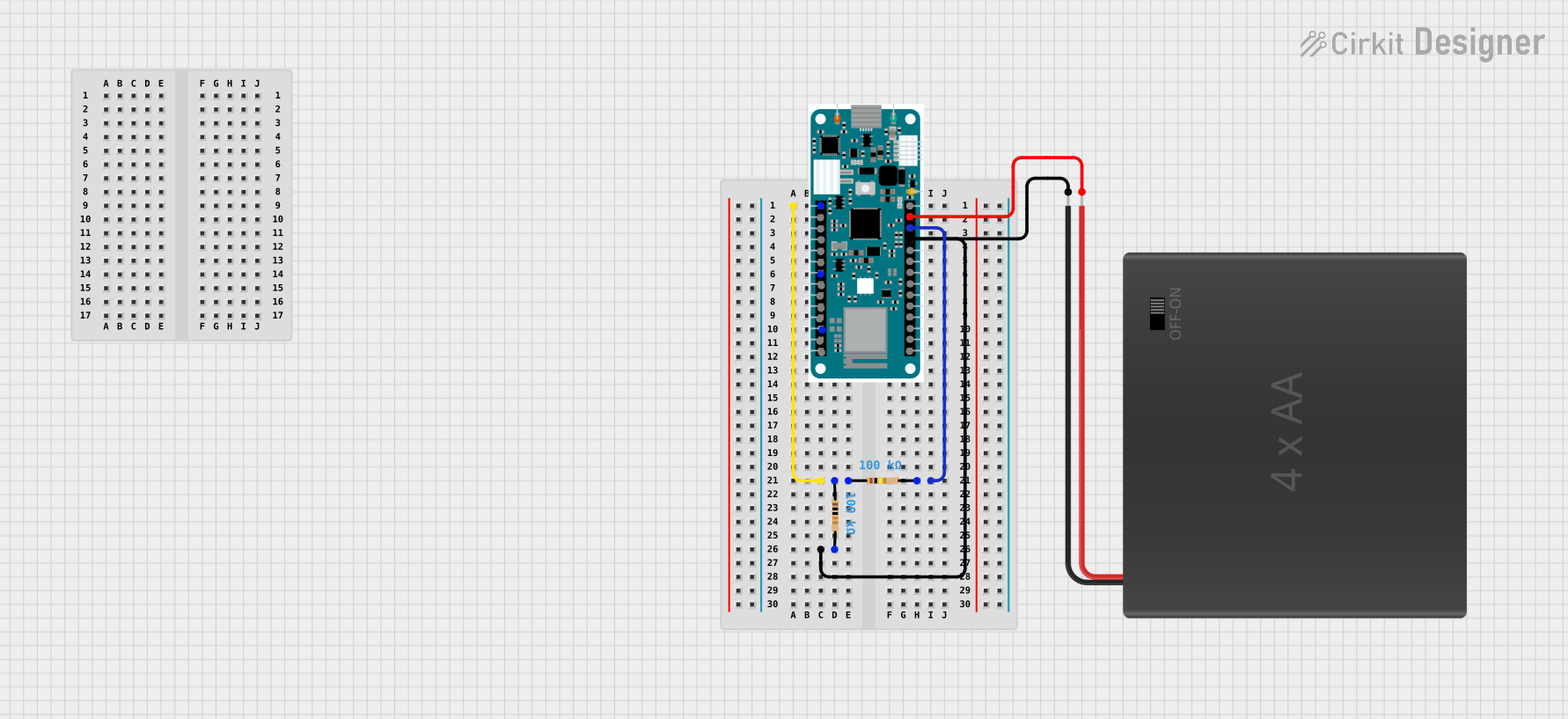
 Open Project in Cirkit Designer
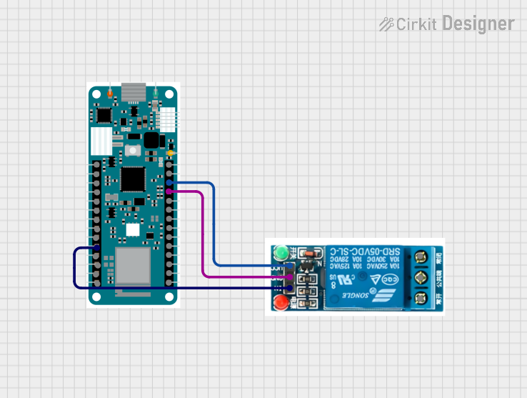
 Open Project in Cirkit Designer
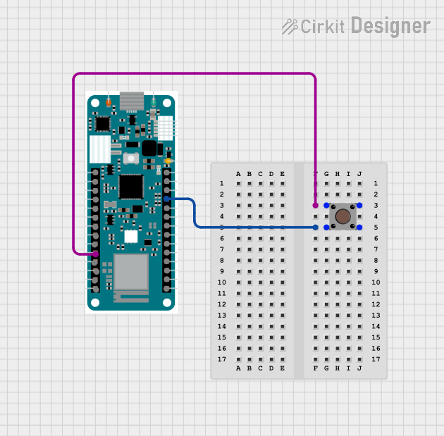
 Open Project in Cirkit Designer
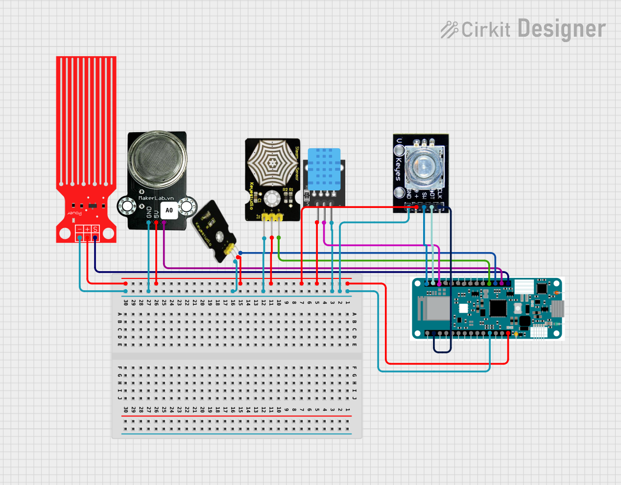
 Open Project in Cirkit Designer
Explore Projects Built with Arduino MKR WiFi 1010

 Open Project in Cirkit Designer
 Open Project in Cirkit Designer
 Open Project in Cirkit Designer
 Open Project in Cirkit Designer
Common Applications and Use Cases
- Smart home devices
- Remote sensor networks
- IoT prototypes
- Wearable technology
- Wireless control systems
Technical Specifications
Key Technical Details
- Microcontroller: Microchip SAMD21 Cortex-M0+ 32bit low power ARM MCU
- Wi-Fi Module: u-blox NINA-W10 series (802.11 b/g/n)
- Operating Voltage: 3.3V
- Input Voltage (recommended): 5V via micro USB or Vin pin
- Input Voltage (limit): 6-20V
- Digital I/O Pins: 8, with 12 PWM and UART
- Analog Input Pins: 7 (ADC 8/10/12 bit)
- Analog Output Pins: 1 (DAC 10 bit)
- DC Current per I/O Pin: 7 mA
- Flash Memory: 256 KB (of which 8 KB used by bootloader)
- SRAM: 32 KB
- Clock Speed: 48 MHz
- LED_BUILTIN: 6
Pin Configuration and Descriptions
| Pin Number | Functionality | Description |
|---|---|---|
| 1 | VIN | Supply voltage to the board when using an external power source |
| 2 | 5V | Regulated power supply used to power the microcontroller and other components |
| 3 | VCC | 3.3V supply generated by the onboard regulator |
| 4 | GND | Ground |
| 5-12 | Digital Pins | Digital input/output pins, PWM capable (D2-D7), UART (D13-D14) |
| 13-19 | Analog Pins | Analog input pins (A1-A6) |
| 20 | RESET | Reset pin, active low |
| 21 | 3.3V | 3.3V output from the onboard regulator |
| 22 | AREF | Analog reference voltage for the ADC |
| 23 | SDA | I2C data line |
| 24 | SCL | I2C clock line |
| 25 | SPI Interfaces | SPI communication lines (MISO, MOSI, SCK) |
| 26 | TX_LED | Transmit LED indicator |
| 27 | RX_LED | Receive LED indicator |
| 28 | LORA | Reserved for future LoRa module |
| 29 | LED_BUILTIN | Built-in LED (pin 6) |
Usage Instructions
How to Use the Component in a Circuit
Powering the Board: The MKR WiFi 1010 can be powered via the micro USB connection or with an external power supply connected to the VIN pin.
Connecting to Wi-Fi: Utilize the onboard NINA-W10 module to connect to Wi-Fi networks. The
WiFiNINAlibrary provided by Arduino is required to enable Wi-Fi functionality.Programming the Board: The board is programmable with the Arduino Software (IDE) or Arduino Web Editor. Select "Arduino MKR WiFi 1010" from the Board Manager.
Digital and Analog Pins: Use the digital and analog pins to interface with various sensors, actuators, and other components.
I2C/SPI Communication: Utilize the I2C (SDA/SCL) and SPI (MISO/MOSI/SCK) pins for communication with compatible devices.
Important Considerations and Best Practices
- Always ensure that the power supply is within the recommended voltage range to prevent damage.
- When using Wi-Fi, take into account the power consumption and ensure a stable power source.
- Use proper decoupling capacitors close to the power pins if the board is experiencing resets during high-current operations.
- Avoid exposing the board to static electricity or physical stress.
- Keep the firmware of the NINA-W10 module updated using the WiFi101 / WiFiNINA Firmware Updater plugin in the Arduino IDE.
Example Code for Arduino UNO
#include <WiFiNINA.h>

// Replace with your network credentials
const char* ssid = "your_network_name";
const char* password = "your_network_password";

void setup() {
  // Initialize serial communication
  Serial.begin(9600);

  // Check for the presence of the WiFi module
  if (WiFi.status() == WL_NO_MODULE) {
    Serial.println("Communication with WiFi module failed!");
    // Don't continue further if the module is not present
    while (true);
  }

  // Attempt to connect to the Wi-Fi network
  while (WiFi.begin(ssid, password) != WL_CONNECTED) {
    Serial.print("Attempting to connect to WPA SSID: ");
    Serial.println(ssid);
    // Wait 5 seconds before retrying
    delay(5000);
  }

  Serial.println("You're connected to the network");
  printCurrentNet();
  printWiFiData();
}

void loop() {
  // Nothing to do here
}

void printWiFiData() {
  // Print the IP address
  IPAddress ip = WiFi.localIP();
  Serial.print("IP Address: ");
  Serial.println(ip);
}

void printCurrentNet() {
  // Print the SSID of the network you're attached to
  Serial.print("SSID: ");
  Serial.println(WiFi.SSID());

  // Print the MAC address of the router you're attached to
  byte bssid[6];
  WiFi.BSSID(bssid);
  Serial.print("BSSID: ");
  Serial.print(bssid[5], HEX);
  Serial.print(":");
  Serial.print(bssid[4], HEX);
  Serial.print(":");
  Serial.print(bssid[3], HEX);
  Serial.print(":");
  Serial.print(bssid[2], HEX);
  Serial.print(":");
  Serial.print(bssid[1], HEX);
  Serial.print(":");
  Serial.println(bssid[0], HEX);
}
Troubleshooting and FAQs
Common Issues Users Might Face
- Wi-Fi Connection Issues: Ensure the network SSID and password are correct. Check the signal strength and router settings.
- Board Not Recognized: Verify the USB cable is working and the board is selected in the Arduino IDE.
- Firmware Update Required: The NINA-W10 module may require a firmware update for optimal performance.
Solutions and Tips for Troubleshooting
- Reset the Board: Press the onboard reset button to restart the board.
- Update Firmware: Use the WiFi101 / WiFiNINA Firmware Updater from the Arduino IDE.
- Check Power Supply: Ensure the board is receiving a stable voltage within the recommended range.
- Serial Monitor: Use the Serial Monitor to debug and check for error messages.
FAQs
Q: Can the MKR WiFi 1010 be powered by a battery? A: Yes, it can be powered by a Li-Po battery connected to the JST connector or other batteries connected to the VIN pin.
Q: Is the board compatible with all Arduino libraries? A: The MKR WiFi 1010 is compatible with most libraries that support the SAMD21 architecture. Some libraries may need updates or modifications.
Q: How do I update the Wi-Fi module firmware? A: Use the WiFi101 / WiFiNINA Firmware Updater plugin available in the Arduino IDE under the Tools menu.
Q: Can I use the MKR WiFi 1010 with the Arduino IoT Cloud? A: Yes, the board is designed to work seamlessly with the Arduino IoT Cloud for easy IoT application development.