How to Use Modulo Dimmer: Examples, Pinouts, and Specs
Introduction
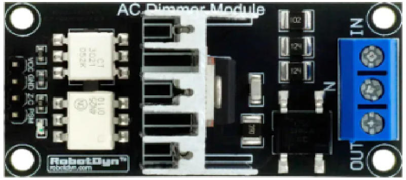
The Modulo Dimmer (RobotDyn AC Light Dimmer Module) is an electronic device designed to control the brightness of AC-powered lighting fixtures. By varying the voltage or current supplied to the load, it enables precise dimming of incandescent, halogen, and some dimmable LED lights. This module is widely used in home automation, theatrical lighting, and energy-saving applications.
Explore Projects Built with Modulo Dimmer
Explore Projects Built with Modulo Dimmer
Common Applications and Use Cases
- Home Automation: Adjust lighting levels for comfort and energy efficiency.
- Theatrical Lighting: Create dynamic lighting effects for stage performances.
- Industrial Use: Control AC loads such as fans or heaters.
- Smart Lighting Systems: Integrate with microcontrollers like Arduino for automated dimming.
Technical Specifications
Key Technical Details
- Manufacturer: RobotDyn
- Part ID: AC Light Dimmer Module
- Input Voltage: 110V-220V AC
- Output Load: 0-200W (for 110V AC) / 0-400W (for 220V AC)
- Control Voltage: 3.3V-5V (compatible with most microcontrollers)
- Zero-Cross Detection: Built-in for precise dimming control
- Isolation: Optocoupler for safe interfacing with low-voltage circuits
- Dimensions: 50mm x 25mm x 20mm
Pin Configuration and Descriptions
The Modulo Dimmer has a 4-pin interface for connecting to a microcontroller and AC load.
| Pin Name | Description |
|---|---|
AC-IN |
AC input terminals for connecting to the mains power supply (110V-220V AC). |
AC-OUT |
AC output terminals for connecting to the load (e.g., light bulb, fan). |
VCC |
Power supply input for the control circuit (3.3V-5V). |
GND |
Ground connection for the control circuit. |
PWM |
Pulse Width Modulation input for dimming control (from microcontroller). |
Z-C |
Zero-cross detection signal output (used for synchronization with AC cycles). |
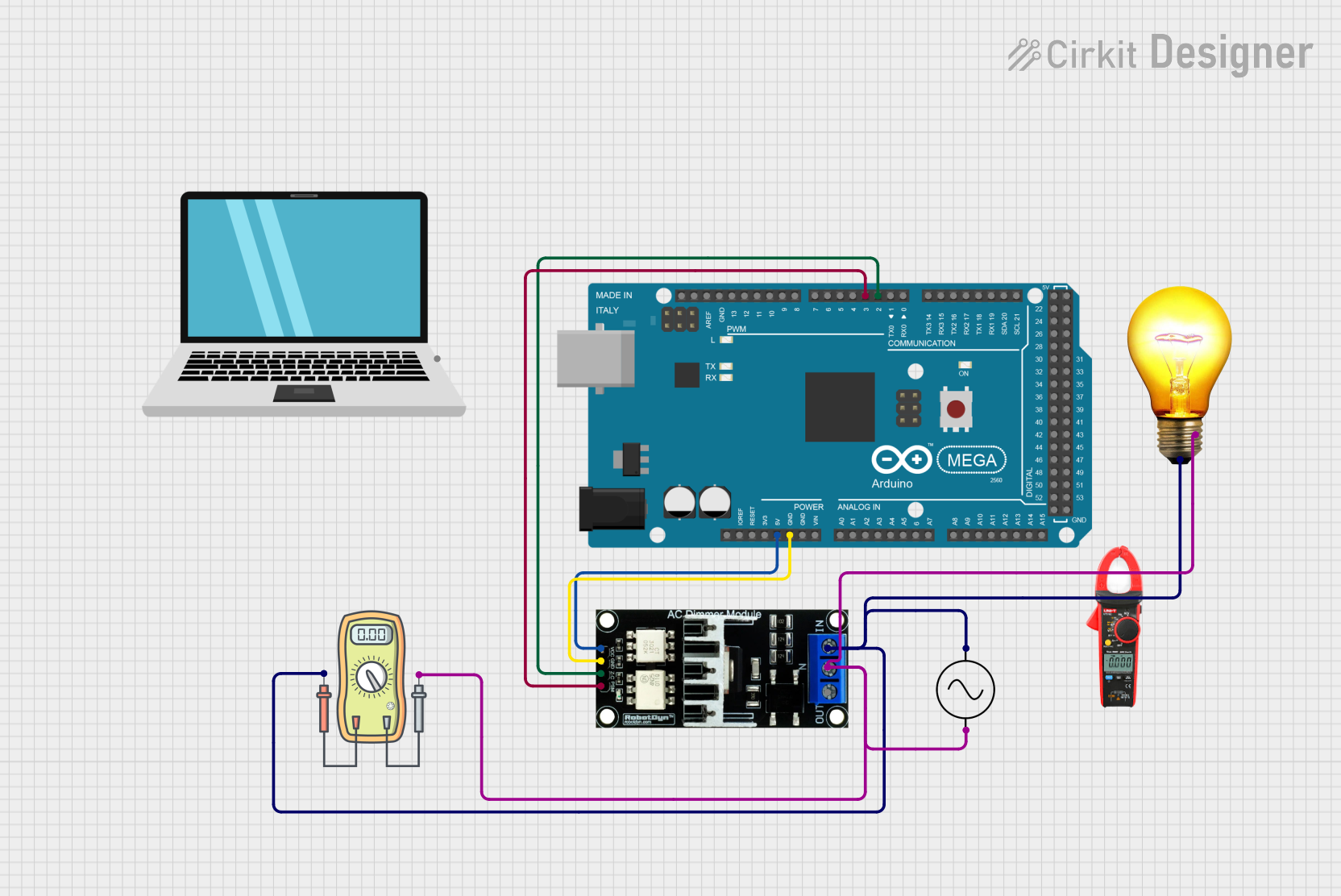
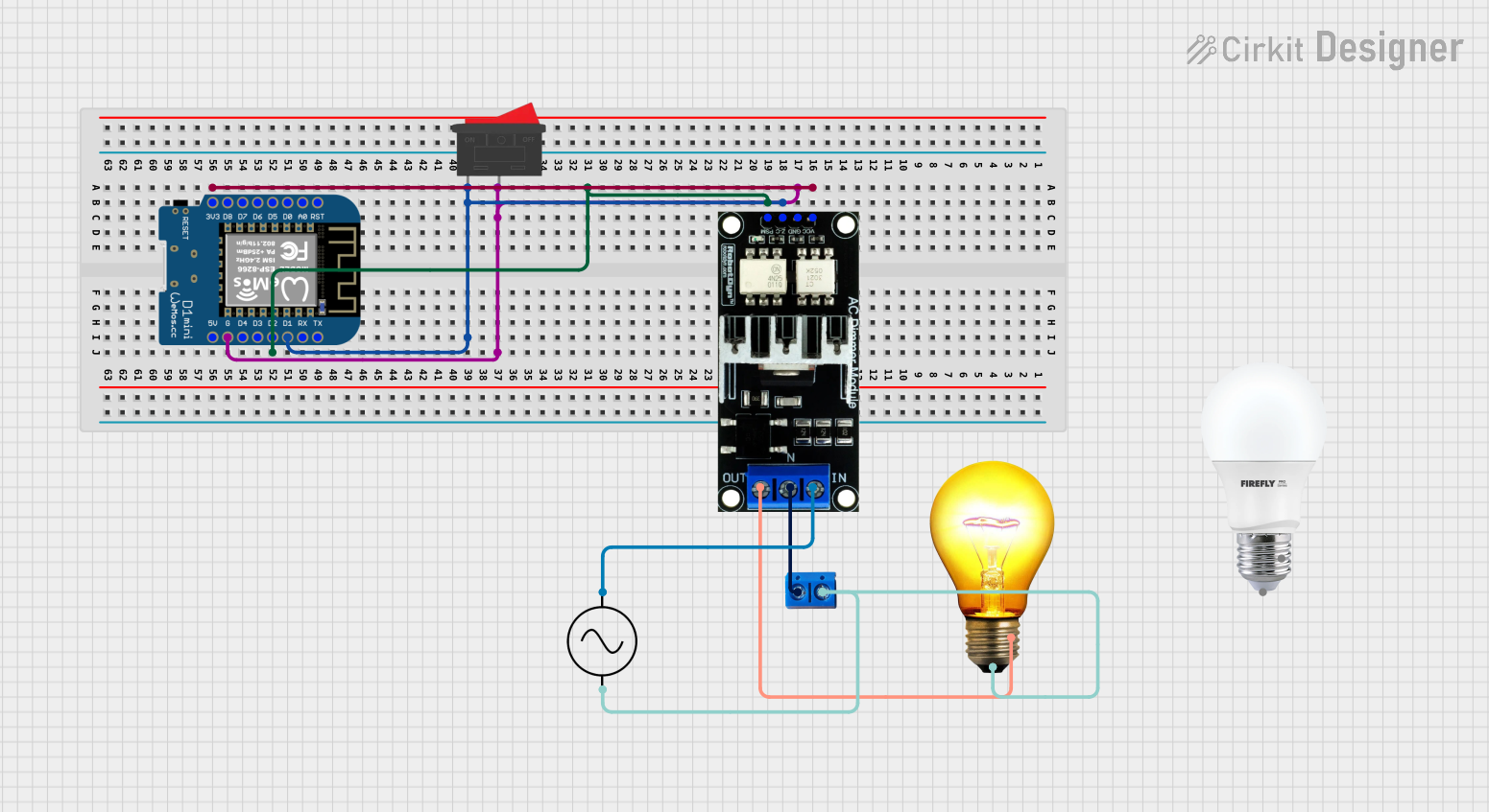
Usage Instructions
How to Use the Modulo Dimmer in a Circuit
Connect the AC Input and Output:
- Connect the
AC-INterminals to the mains power supply (110V-220V AC). - Connect the
AC-OUTterminals to the load (e.g., a dimmable light bulb).
- Connect the
Connect to a Microcontroller:
- Connect the
VCCandGNDpins to the 3.3V or 5V power supply of your microcontroller. - Connect the
PWMpin to a PWM-capable pin on the microcontroller. - Optionally, connect the
Z-Cpin to a digital input pin for zero-cross detection.
- Connect the
Write Control Code:
- Use the PWM signal to control the brightness of the connected load.
- Synchronize the PWM signal with the zero-cross detection signal for smooth dimming.
Important Considerations and Best Practices
- Safety First: Always handle the module with care when working with high-voltage AC power. Ensure proper insulation and avoid touching live components.
- Load Compatibility: Verify that the connected load is dimmable and within the module's power rating.
- Zero-Cross Synchronization: For smooth dimming, use the zero-cross detection signal to synchronize the PWM signal with the AC mains frequency.
- Heat Dissipation: Ensure adequate ventilation or heat sinking if the module operates near its maximum power rating.
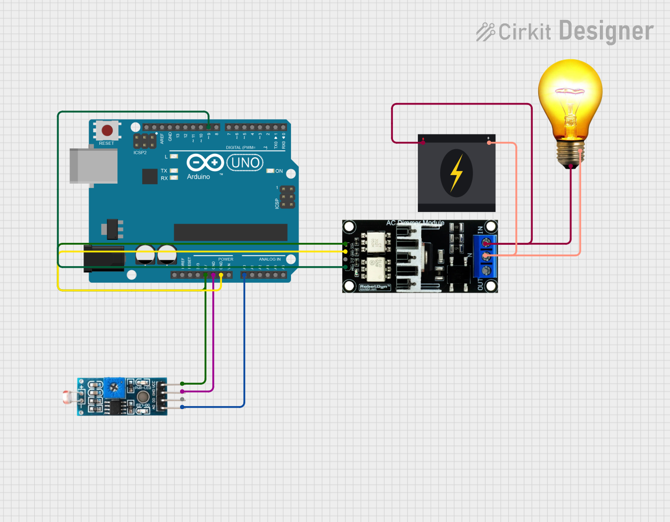
Example Code for Arduino UNO
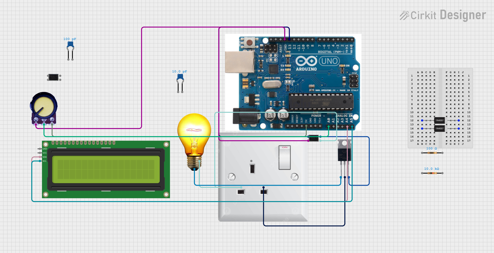
Below is an example of how to use the Modulo Dimmer with an Arduino UNO to control the brightness of a light bulb.
/*
  Example Code for RobotDyn AC Light Dimmer Module
  This code demonstrates how to control the brightness of a light bulb
  using PWM and zero-cross detection with an Arduino UNO.
*/

#define ZC_PIN 2    // Pin connected to the Zero-Cross detection signal
#define PWM_PIN 3   // Pin connected to the PWM input of the dimmer module

volatile boolean zeroCross = false; // Flag for zero-cross detection
int dimValue = 128;                 // Brightness level (0-255)
int delayTime;                      // Delay time for dimming

void zeroCrossISR() {
  // Interrupt Service Routine for zero-cross detection
  zeroCross = true;
}

void setup() {
  pinMode(ZC_PIN, INPUT);           // Set Zero-Cross pin as input
  pinMode(PWM_PIN, OUTPUT);         // Set PWM pin as output
  attachInterrupt(digitalPinToInterrupt(ZC_PIN), zeroCrossISR, RISING);
}

void loop() {
  if (zeroCross) {
    zeroCross = false;              // Reset zero-cross flag
    delayTime = (128 - dimValue) * 75; // Calculate delay for dimming
    delayMicroseconds(delayTime);   // Wait for the calculated delay
    digitalWrite(PWM_PIN, HIGH);    // Turn on the dimmer
    delayMicroseconds(10);          // Keep it on for a short duration
    digitalWrite(PWM_PIN, LOW);     // Turn off the dimmer
  }
}
Troubleshooting and FAQs
Common Issues and Solutions
The light does not dim or flickers:
- Ensure the load is dimmable (e.g., incandescent or dimmable LED).
- Verify proper synchronization with the zero-cross signal.
- Check the PWM signal from the microcontroller.
The module overheats:
- Ensure the load does not exceed the module's power rating.
- Provide adequate ventilation or heat sinking.
No response from the module:
- Verify all connections, especially the AC input and output.
- Check the microcontroller's PWM output and ensure it is connected to the correct pin.
Zero-cross detection not working:
- Ensure the
Z-Cpin is properly connected to the microcontroller. - Check for noise or interference in the AC mains supply.
- Ensure the
FAQs
Can I use this module with a 3.3V microcontroller?
Yes, the module is compatible with both 3.3V and 5V logic levels.Is this module suitable for non-dimmable LEDs?
No, non-dimmable LEDs may not work correctly and could be damaged.Can I control multiple dimmers with one microcontroller?
Yes, but ensure each dimmer has its own zero-cross detection and PWM control pin.What happens if I exceed the power rating?
Exceeding the power rating may damage the module or cause overheating. Always stay within the specified limits.
This concludes the documentation for the RobotDyn AC Light Dimmer Module.