How to Use SD30CRMA MPPT: Examples, Pinouts, and Specs
Introduction
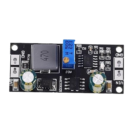
The SD30CRMA MPPT is a Maximum Power Point Tracking (MPPT) solar charge controller designed to optimize the power output from solar panels by continuously tracking and adjusting to the maximum power point. It ensures efficient energy conversion and battery charging in solar power systems. This component is essential for maximizing the efficiency of solar power systems, making it a popular choice for both residential and commercial solar installations.
Explore Projects Built with SD30CRMA MPPT
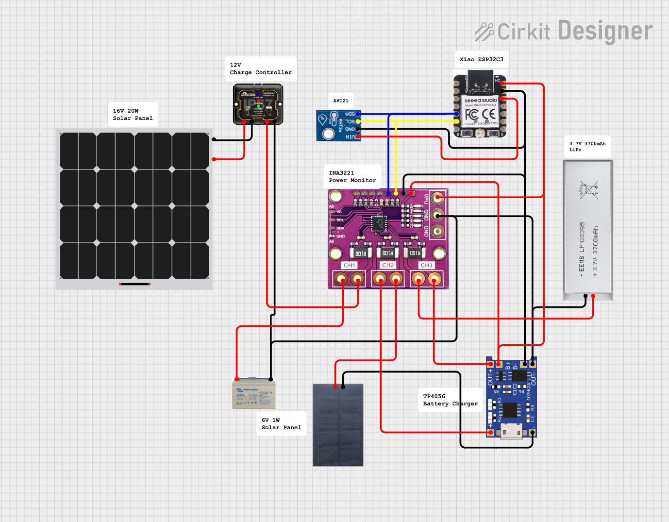

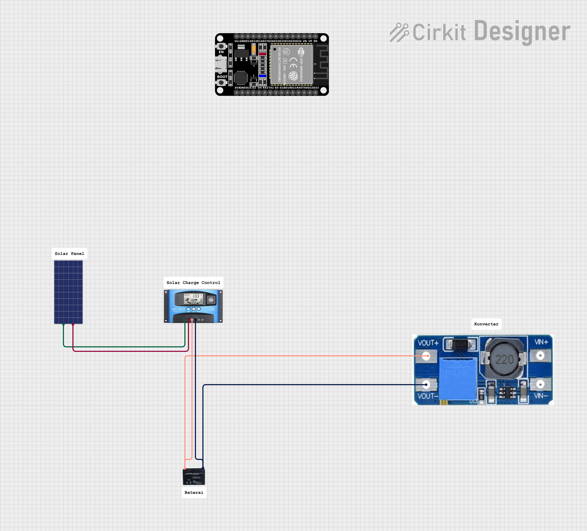
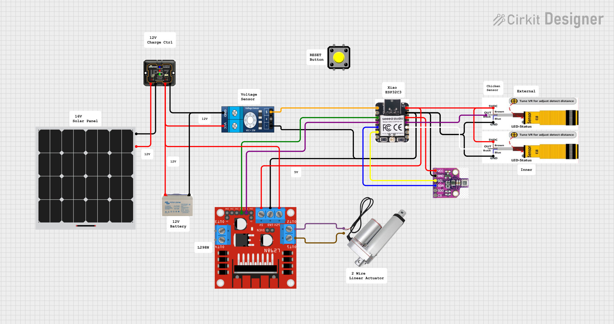
Explore Projects Built with SD30CRMA MPPT
Common Applications and Use Cases
- Residential solar power systems
- Commercial solar installations
- Off-grid solar power systems
- Solar-powered battery charging stations
- Solar energy research and development
Technical Specifications
Key Technical Details
| Parameter | Value |
|---|---|
| Maximum Input Voltage | 100V |
| Maximum Input Current | 30A |
| Maximum Output Current | 30A |
| Battery Voltage Range | 12V/24V/48V (Auto Select) |
| Efficiency | Up to 98% |
| Operating Temperature | -20°C to 60°C |
| Dimensions | 200mm x 150mm x 60mm |
| Weight | 1.5 kg |
Pin Configuration and Descriptions
| Pin Number | Pin Name | Description |
|---|---|---|
| 1 | PV+ | Positive terminal for solar panel input |
| 2 | PV- | Negative terminal for solar panel input |
| 3 | BAT+ | Positive terminal for battery connection |
| 4 | BAT- | Negative terminal for battery connection |
| 5 | LOAD+ | Positive terminal for load connection |
| 6 | LOAD- | Negative terminal for load connection |
| 7 | RS485 A | RS485 communication port (A) |
| 8 | RS485 B | RS485 communication port (B) |
| 9 | TEMP | Temperature sensor input |
| 10 | GND | Ground |
Usage Instructions
How to Use the Component in a Circuit
Connect the Solar Panel:
- Connect the positive terminal of the solar panel to the
PV+pin. - Connect the negative terminal of the solar panel to the
PV-pin.
- Connect the positive terminal of the solar panel to the
Connect the Battery:
- Connect the positive terminal of the battery to the
BAT+pin. - Connect the negative terminal of the battery to the
BAT-pin.
- Connect the positive terminal of the battery to the
Connect the Load (Optional):
- Connect the positive terminal of the load to the
LOAD+pin. - Connect the negative terminal of the load to the
LOAD-pin.
- Connect the positive terminal of the load to the
Connect the Temperature Sensor (Optional):
- Connect the temperature sensor to the
TEMPpin.
- Connect the temperature sensor to the
RS485 Communication (Optional):
- Connect the RS485 communication lines to the
RS485 AandRS485 Bpins for remote monitoring and control.
- Connect the RS485 communication lines to the
Important Considerations and Best Practices
- Ensure Proper Polarity: Always double-check the polarity of the connections to avoid damaging the controller or connected devices.
- Use Appropriate Wire Gauge: Use wires with appropriate gauge to handle the current without significant voltage drop or overheating.
- Install in a Well-Ventilated Area: Ensure the controller is installed in a well-ventilated area to prevent overheating.
- Regular Maintenance: Periodically check the connections and clean any dust or debris from the controller to maintain optimal performance.
Troubleshooting and FAQs
Common Issues Users Might Face
No Power Output:
- Solution: Check the connections to ensure proper polarity and secure connections. Verify that the solar panel is generating power.
Overheating:
- Solution: Ensure the controller is installed in a well-ventilated area. Check for any obstructions blocking airflow.
Battery Not Charging:
- Solution: Verify the battery connections and ensure the battery voltage is within the supported range. Check the solar panel output.
Communication Failure (RS485):
- Solution: Check the RS485 connections and ensure the correct wiring. Verify the communication settings on the monitoring device.
FAQs
Q1: Can the SD30CRMA MPPT be used with any type of battery?
- A1: The SD30CRMA MPPT supports 12V, 24V, and 48V batteries. Ensure the battery voltage is within this range.
Q2: How do I know if the controller is working correctly?
- A2: The controller has LED indicators that show the status of the solar panel, battery, and load. Refer to the user manual for detailed information on the LED indicators.
Q3: Can I connect multiple solar panels to the SD30CRMA MPPT?
- A3: Yes, you can connect multiple solar panels in series or parallel, as long as the combined voltage and current do not exceed the controller's maximum input ratings.
Q4: Is it necessary to use the temperature sensor?
- A4: The temperature sensor is optional but recommended for optimal battery charging, as it allows the controller to adjust the charging parameters based on the battery temperature.
Arduino UNO Integration Example
If you want to monitor the SD30CRMA MPPT using an Arduino UNO, you can use the RS485 communication. Below is an example code to read data from the controller:
#include <SoftwareSerial.h>

SoftwareSerial rs485(10, 11); // RX, TX

void setup() {
  Serial.begin(9600);
  rs485.begin(9600);
  pinMode(10, INPUT); // RX
  pinMode(11, OUTPUT); // TX
}

void loop() {
  if (rs485.available()) {
    String data = "";
    while (rs485.available()) {
      char c = rs485.read();
      data += c;
    }
    Serial.println(data); // Print the received data to the Serial Monitor
  }
  delay(1000); // Wait for 1 second before reading again
}
Note: Ensure you have the appropriate RS485 module connected to the Arduino UNO for communication.
This documentation provides a comprehensive guide to using the SD30CRMA MPPT solar charge controller, ensuring efficient and reliable operation in your solar power system.