
How to Use KY-003 Hall Effect Sensor: Examples, Pinouts, and Specs
 Design with KY-003 Hall Effect Sensor in Cirkit Designer
Introduction
The KY-003 Hall Effect Sensor is a compact and versatile device designed to detect the presence of a magnetic field. It operates by converting magnetic field strength into a digital signal, which can be easily interpreted by microcontrollers or other digital systems. This sensor is widely used in applications such as proximity sensing, speed detection, and position sensing. Its small size and ease of use make it a popular choice for hobbyists and professionals alike.
Explore Projects Built with KY-003 Hall Effect Sensor
 Open Project in Cirkit Designer
 Open Project in Cirkit Designer
 Open Project in Cirkit Designer
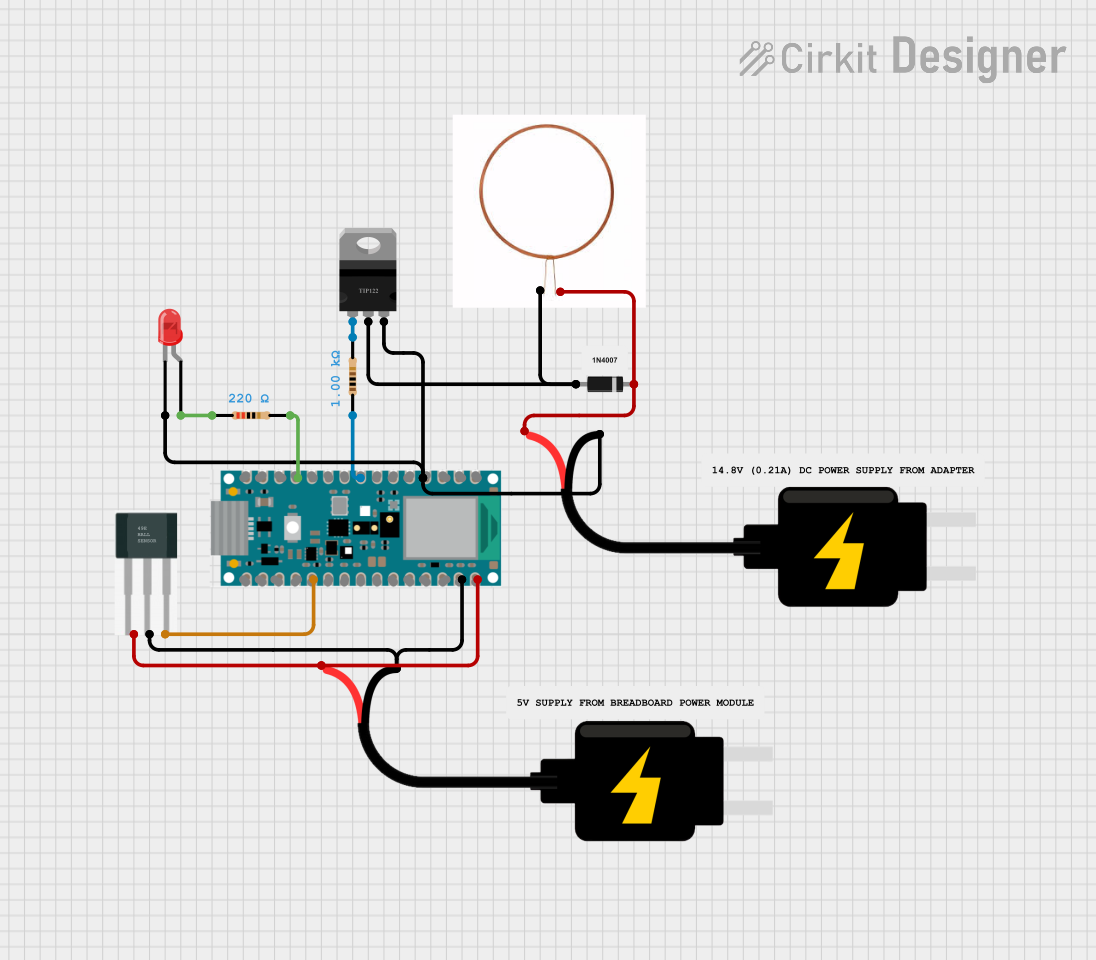 Open Project in Cirkit Designer
Explore Projects Built with KY-003 Hall Effect Sensor
Open Project in Cirkit DesignerOpen Project in Cirkit DesignerOpen Project in Cirkit DesignerOpen Project in Cirkit DesignerTechnical Specifications
- Operating Voltage: 3.3V to 5V
- Output Type: Digital (High/Low)
- Current Consumption: 4mA (typical)
- Magnetic Sensitivity: Detects both North and South poles of a magnet
- Operating Temperature: -40°C to 85°C
- Dimensions: 18.5mm x 15mm x 7mm (approx.)
Pin Configuration and Descriptions
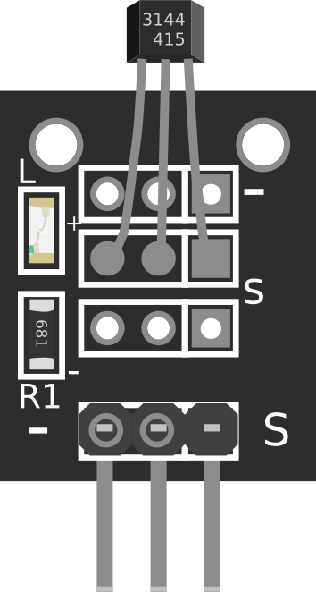
The KY-003 Hall Effect Sensor has three pins, as described in the table below:
| Pin Number | Pin Name | Description |
|---|---|---|
| 1 | Signal (S) | Outputs a digital HIGH (1) when a magnetic field is detected. |
| 2 | VCC | Connects to the positive power supply (3.3V to 5V). |
| 3 | GND | Connects to the ground of the power supply. |
Usage Instructions
How to Use the KY-003 in a Circuit
- Power the Sensor: Connect the VCC pin to a 3.3V or 5V power source and the GND pin to the ground.
- Connect the Signal Pin: Attach the Signal (S) pin to a digital input pin on your microcontroller (e.g., Arduino UNO).
- Place a Magnet: Position a magnet near the sensor. The sensor will output a HIGH signal when it detects a magnetic field and a LOW signal otherwise.
- Add a Pull-Down Resistor (Optional): For stable operation, you can connect a pull-down resistor (e.g., 10kΩ) between the Signal pin and GND.
Important Considerations and Best Practices
- Ensure the sensor is not exposed to magnetic fields stronger than its rated capacity, as this may damage the sensor or cause inaccurate readings.
- Avoid placing the sensor near sources of electromagnetic interference (EMI), such as motors or high-frequency circuits.
- Use a decoupling capacitor (e.g., 0.1µF) between VCC and GND to reduce noise in the power supply.
Example Code for Arduino UNO
The following code demonstrates how to use the KY-003 Hall Effect Sensor with an Arduino UNO. The onboard LED (connected to pin 13) will light up when a magnetic field is detected.
// Define the pin connected to the KY-003 Signal pin
const int hallSensorPin = 2; // Digital pin 2
const int ledPin = 13;       // Onboard LED pin

void setup() {
  pinMode(hallSensorPin, INPUT); // Set the sensor pin as input
  pinMode(ledPin, OUTPUT);       // Set the LED pin as output
  Serial.begin(9600);            // Initialize serial communication
}

void loop() {
  int sensorState = digitalRead(hallSensorPin); // Read the sensor state

  if (sensorState == HIGH) {
    // Magnetic field detected
    digitalWrite(ledPin, HIGH); // Turn on the LED
    Serial.println("Magnetic field detected!");
  } else {
    // No magnetic field detected
    digitalWrite(ledPin, LOW);  // Turn off the LED
    Serial.println("No magnetic field detected.");
  }

  delay(100); // Small delay for stability
}
Troubleshooting and FAQs
Common Issues
The sensor does not detect the magnetic field.
- Solution: Ensure the magnet is strong enough and positioned close to the sensor. Verify that the sensor is powered correctly (3.3V to 5V).
The output signal is unstable or noisy.
- Solution: Add a pull-down resistor (e.g., 10kΩ) between the Signal pin and GND. Use a decoupling capacitor (e.g., 0.1µF) between VCC and GND to filter noise.
The sensor gets hot or stops working.
- Solution: Check the power supply voltage. Ensure it does not exceed the sensor's maximum rating of 5V.
FAQs
Q: Can the KY-003 detect both poles of a magnet?
A: Yes, the KY-003 can detect both the North and South poles of a magnet.Q: Can I use the KY-003 with a 3.3V microcontroller?
A: Yes, the KY-003 operates within a voltage range of 3.3V to 5V, making it compatible with 3.3V systems.Q: What is the maximum distance at which the sensor can detect a magnet?
A: The detection range depends on the strength of the magnet. Typically, small magnets need to be within a few millimeters of the sensor.Q: Can I use multiple KY-003 sensors in the same circuit?
A: Yes, you can use multiple sensors, but ensure each sensor has its own pull-down resistor if needed, and avoid interference between sensors.
This documentation provides a comprehensive guide to understanding and using the KY-003 Hall Effect Sensor effectively.