How to Use 1000BASE-T Media Converter MC220L: Examples, Pinouts, and Specs

 Design with 1000BASE-T Media Converter MC220L in Cirkit Designer
Introduction
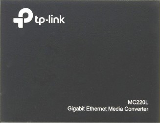
The 1000BASE-T Media Converter MC220L, manufactured by GPS, is an essential device for extending the reach of your network. It converts network signals from copper-based Ethernet cables (1000BASE-T) to optical fiber links, allowing for long-distance transmission that is not susceptible to electromagnetic interference. This converter is commonly used in enterprise networks, data centers, and metropolitan area networks (MANs) where distance, signal integrity, and bandwidth are critical.
Explore Projects Built with 1000BASE-T Media Converter MC220L

 Open Project in Cirkit Designer
 Open Project in Cirkit Designer
 Open Project in Cirkit Designer
 Open Project in Cirkit Designer
Explore Projects Built with 1000BASE-T Media Converter MC220L

 Open Project in Cirkit Designer
 Open Project in Cirkit Designer
 Open Project in Cirkit Designer
 Open Project in Cirkit Designer
Common Applications and Use Cases
- Extending Ethernet connections over long distances
- Connecting copper-based networks to fiber optic infrastructure
- Ensuring high-speed data transmission with minimal signal degradation
- Use in harsh industrial environments where electromagnetic interference is a concern
Technical Specifications
Key Technical Details
- Standards Compliance: IEEE 802.3ab, IEEE 802.3z, IEEE 802.3x
- Data Rate: 1000 Mbps for both copper and fiber ports
- Fiber Type: Single-mode/Multi-mode
- Wavelength: 850nm (Multi-mode), 1310/1550nm (Single-mode)
- Maximum Fiber Cable Distance: up to 10 km (Single-mode), 550 m (Multi-mode)
- Connectors: One RJ45 (copper), one SFP slot (fiber)
- LED Indicators: PWR, Link/Act for both copper and fiber ports
- Power Supply: External power adapter
Pin Configuration and Descriptions
| Pin Number | Description | Notes |
|---|---|---|
| 1 | TX+ (Transmit Plus) | Copper port (RJ45 connector) |
| 2 | TX- (Transmit Minus) | Copper port (RJ45 connector) |
| 3 | RX+ (Receive Plus) | Copper port (RJ45 connector) |
| 6 | RX- (Receive Minus) | Copper port (RJ45 connector) |
| - | Fiber Port | SFP slot for fiber module |
Note: The RJ45 connector uses pins 1, 2, 3, and 6 for Ethernet communication as per the T568B wiring standard.
Usage Instructions
How to Use the Component in a Circuit
Connecting the Copper Interface:
- Connect an Ethernet cable from the network switch or computer to the RJ45 port of the MC220L.
Installing the Fiber Module:
- Insert a compatible SFP module into the SFP slot of the MC220L.
- Connect the fiber optic cable to the SFP module.
Powering the Device:
- Connect the external power adapter to the MC220L and plug it into an electrical outlet.
Verifying the Connection:
- Check the LED indicators for proper operation. A solid or blinking light on the Link/Act indicator signifies a successful connection.
Important Considerations and Best Practices
- Ensure that the SFP module and fiber optic cable types match and are compatible with the MC220L.
- Use high-quality cables and connectors to minimize signal loss.
- Avoid bending the fiber optic cable sharply, as this can cause physical damage and signal degradation.
- Keep the device and fiber connections clean to prevent dust and debris from affecting the signal quality.
Troubleshooting and FAQs
Common Issues Users Might Face
No Link Light on Fiber Port:
- Check if the SFP module is properly seated in the slot.
- Ensure that the fiber optic cable is connected correctly and is not damaged.
- Verify that the SFP module type matches the fiber type (single-mode or multi-mode).
No Data Transmission:
- Confirm that the network settings on the connected devices are correctly configured.
- Check for any possible IP address conflicts.
- Ensure that the Ethernet cable is functioning and properly connected.
Solutions and Tips for Troubleshooting
- If the LED indicators do not light up, check the power supply and cable connections.
- For intermittent connection issues, try replacing the cables or SFP module to rule out hardware faults.
- Clean the fiber connectors with appropriate tools to remove any dust or debris.
FAQs
Q: Can the MC220L be used with both single-mode and multi-mode fiber? A: Yes, but you must use the appropriate SFP module for the type of fiber you are connecting.
Q: What is the maximum distance the MC220L can transmit over fiber? A: The maximum distance depends on the fiber type and SFP module used, up to 10 km for single-mode and 550 m for multi-mode.
Q: Does the MC220L support auto-negotiation for speed and duplex settings? A: Yes, the MC220L supports auto-negotiation for optimal speed and duplex settings.
Q: Can I use the MC220L in a daisy-chain configuration? A: The MC220L is typically used for point-to-point connections. Daisy-chaining is not recommended as it can introduce latency and reduce network performance.
For further assistance, please contact GPS customer support or refer to the manufacturer's website for more detailed information on the MC220L Media Converter.