How to Use ESP32 Baseboard: Examples, Pinouts, and Specs
Introduction
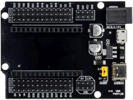
The ESP32 Baseboard (Manufacturer Part ID: ESP32Baseboard30p) is a development board designed by Espressif. It integrates the powerful ESP32 microcontroller, which features dual-core processing, built-in Wi-Fi, and Bluetooth capabilities. This baseboard provides a versatile platform for prototyping Internet of Things (IoT) applications, enabling seamless connectivity and control. With its 30-pin configuration, the ESP32 Baseboard offers multiple GPIO pins for interfacing with sensors, actuators, and other peripherals.
Explore Projects Built with ESP32 Baseboard


Explore Projects Built with ESP32 Baseboard
Common Applications and Use Cases
- IoT devices and smart home automation
- Wireless sensor networks
- Wearable technology
- Robotics and control systems
- Data logging and remote monitoring
- Prototyping Bluetooth Low Energy (BLE) applications
Technical Specifications
Key Technical Details
| Parameter | Value |
|---|---|
| Microcontroller | ESP32 (dual-core, 32-bit Xtensa LX6 CPU) |
| Clock Speed | Up to 240 MHz |
| Flash Memory | 4 MB (varies by model) |
| SRAM | 520 KB |
| Wi-Fi | 802.11 b/g/n (2.4 GHz) |
| Bluetooth | v4.2 BR/EDR and BLE |
| Operating Voltage | 3.3V |
| Input Voltage (VIN) | 5V (via USB or external power supply) |
| GPIO Pins | 30 (multipurpose, including ADC, PWM, etc.) |
| Communication Interfaces | UART, SPI, I2C, I2S, CAN, Ethernet |
| Power Consumption | ~160 mA (active mode) |
| Dimensions | 57 mm x 25 mm |
Pin Configuration and Descriptions
The ESP32 Baseboard features a 30-pin layout. Below is the pinout description:
| Pin Number | Pin Name | Functionality |
|---|---|---|
| 1 | GND | Ground |
| 2 | VIN | Power input (5V) |
| 3 | 3V3 | 3.3V output |
| 4 | EN | Enable pin (active high) |
| 5 | IO0 | GPIO0, boot mode selection |
| 6 | IO1 | GPIO1, UART TX |
| 7 | IO2 | GPIO2, ADC, PWM |
| 8 | IO3 | GPIO3, UART RX |
| 9 | IO4 | GPIO4, ADC, PWM |
| 10 | IO5 | GPIO5, ADC, PWM |
| 11 | IO12 | GPIO12, ADC, PWM |
| 12 | IO13 | GPIO13, ADC, PWM |
| 13 | IO14 | GPIO14, ADC, PWM |
| 14 | IO15 | GPIO15, ADC, PWM |
| 15 | IO16 | GPIO16, ADC, PWM |
| 16 | IO17 | GPIO17, ADC, PWM |
| 17 | IO18 | GPIO18, SPI CLK |
| 18 | IO19 | GPIO19, SPI MISO |
| 19 | IO21 | GPIO21, I2C SDA |
| 20 | IO22 | GPIO22, I2C SCL |
| 21 | IO23 | GPIO23, SPI MOSI |
| 22 | IO25 | GPIO25, ADC, PWM |
| 23 | IO26 | GPIO26, ADC, PWM |
| 24 | IO27 | GPIO27, ADC, PWM |
| 25 | IO32 | GPIO32, ADC, PWM |
| 26 | IO33 | GPIO33, ADC, PWM |
| 27 | IO34 | GPIO34, ADC (input only) |
| 28 | IO35 | GPIO35, ADC (input only) |
| 29 | RXD0 | UART0 RX |
| 30 | TXD0 | UART0 TX |
Usage Instructions
How to Use the ESP32 Baseboard in a Circuit
Powering the Board:
- Connect the ESP32 Baseboard to your computer via a USB cable for power and programming.
- Alternatively, supply 5V to the VIN pin or 3.3V to the 3V3 pin for external power.
Programming the Board:
- Install the Arduino IDE or Espressif's ESP-IDF development environment.
- Add the ESP32 board support package to the Arduino IDE by including the appropriate URL in the Board Manager.
- Select "ESP32 Dev Module" as the board type and the correct COM port.
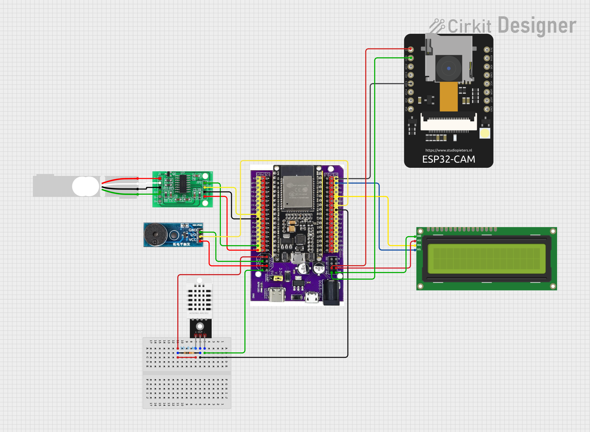
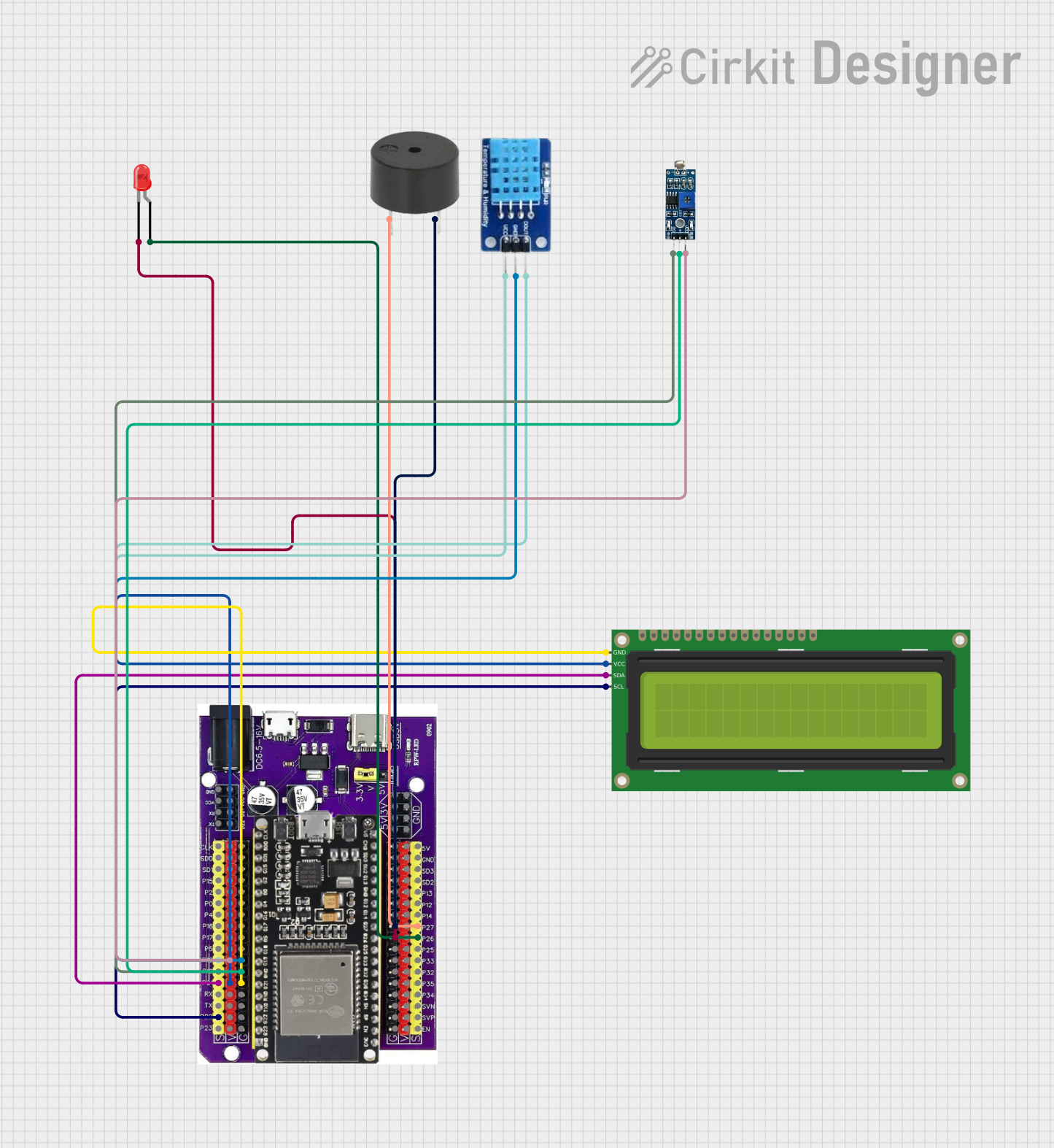
Connecting Peripherals:
- Use the GPIO pins to connect sensors, actuators, or other devices.
- Ensure that the voltage levels of connected peripherals are compatible with the 3.3V logic of the ESP32.
Uploading Code:
- Write your program in the Arduino IDE or ESP-IDF.
- Click the upload button to flash the code to the ESP32 Baseboard.
Important Considerations and Best Practices
- Voltage Levels: The GPIO pins operate at 3.3V. Avoid applying 5V directly to the pins to prevent damage.
- Boot Mode: Ensure GPIO0 is pulled low during boot to enter programming mode.
- Power Supply: Use a stable power source to avoid unexpected resets or instability.
- Wi-Fi and Bluetooth: Avoid placing the board near metal objects or enclosures that may interfere with wireless signals.
Example Code for Arduino UNO Integration
Below is an example of using the ESP32 Baseboard to blink an LED connected to GPIO2:
// Example: Blink an LED connected to GPIO2 on the ESP32 Baseboard

// Define the GPIO pin for the LED
const int ledPin = 2;

void setup() {
  // Initialize the LED pin as an output
  pinMode(ledPin, OUTPUT);
}

void loop() {
  // Turn the LED on
  digitalWrite(ledPin, HIGH);
  delay(1000); // Wait for 1 second

  // Turn the LED off
  digitalWrite(ledPin, LOW);
  delay(1000); // Wait for 1 second
}
Troubleshooting and FAQs
Common Issues and Solutions
The ESP32 Baseboard is not detected by the computer:
- Ensure the USB cable is functional and supports data transfer.
- Install the correct USB-to-serial driver for the ESP32.
Code upload fails:
- Check that GPIO0 is pulled low during programming.
- Verify the correct COM port and board type are selected in the IDE.
Wi-Fi connection issues:
- Ensure the Wi-Fi credentials in your code are correct.
- Check for interference or weak signal strength.
Board resets unexpectedly:
- Verify that the power supply is stable and sufficient.
- Avoid connecting peripherals that draw excessive current.
FAQs
Q: Can I use 5V sensors with the ESP32 Baseboard?
A: Yes, but you will need a level shifter to step down the voltage to 3.3V for the GPIO pins.
Q: How do I reset the ESP32 Baseboard?
A: Press the reset button on the board or power cycle the device.
Q: Can the ESP32 Baseboard run on battery power?
A: Yes, you can connect a 3.7V LiPo battery to the VIN pin, but ensure proper regulation.
Q: Is the ESP32 Baseboard compatible with Arduino libraries?
A: Yes, most Arduino libraries are compatible with the ESP32, but some may require modifications.