Cirkit Designer Logo
Cirkit Designer
Your all-in-one circuit design IDE
Home / 
Component Documentation

How to Use Module LDR: Examples, Pinouts, and Specs

Image of Module LDR
Cirkit Designer LogoDesign with Module LDR in Cirkit Designer

Introduction

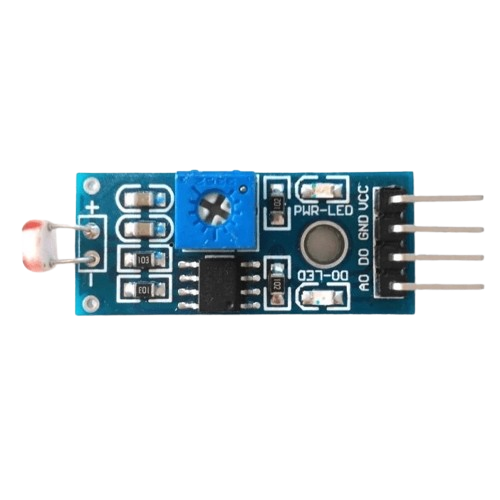
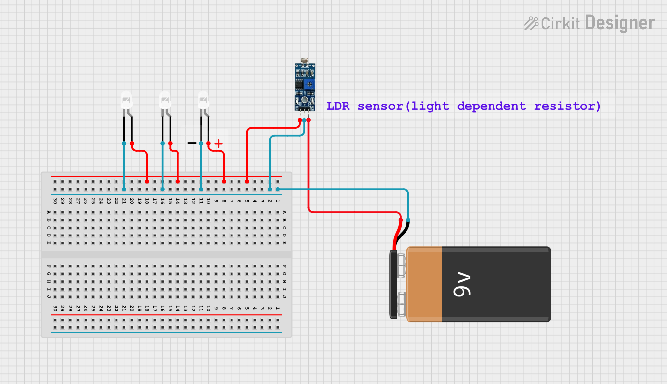
The Light Dependent Resistor (LDR) module is a photosensitive device that is widely used in various light-sensing applications. The resistance of the LDR decreases with increasing light intensity, making it an essential component for projects that require light detection, such as automatic night lights, alarm systems, and environmental monitoring.

Explore Projects Built with Module LDR

Use Cirkit Designer to design, explore, and prototype these projects online. Some projects support real-time simulation. Click "Open Project" to start designing instantly!
Arduino UNO Controlled LDR and LED Circuit
Image of LDR: A project utilizing Module LDR in a practical application
This circuit consists of an Arduino UNO connected to an LDR (Light Dependent Resistor) module and a red LED. The LDR module is powered by the Arduino and its analog output (AO) is connected to the Arduino's analog input (A0) for light intensity measurement. The red LED is connected to a digital output (D13) on the Arduino, with its cathode grounded, allowing the Arduino to control the LED based on the LDR's readings or other logic programmed into the Arduino.
Cirkit Designer LogoOpen Project in Cirkit Designer
Arduino UNO Based LDR-Controlled LED Indicator
Image of switch: A project utilizing Module LDR in a practical application
This circuit features an Arduino UNO connected to an LDR (Light Dependent Resistor) module and an LED with a series resistor. The LDR module is powered by the Arduino's 5V output and its digital output (DO) is connected to the Arduino's analog input A0, potentially for light level sensing. The LED is connected to digital pin D13 through a 220 Ohm resistor, which could be used to indicate the status or the result of the LDR's light sensing.
Cirkit Designer LogoOpen Project in Cirkit Designer
Arduino UNO Light-Activated LED with LDR Sensor
Image of switch: A project utilizing Module LDR in a practical application
This circuit uses an Arduino UNO to read the output from an LDR module and control an LED. The LDR module is powered by the Arduino and its digital output is read on pin A0. Based on the LDR reading, the Arduino turns the LED on or off through a 220-ohm resistor connected to pin D13.
Cirkit Designer LogoOpen Project in Cirkit Designer
Battery-Powered LDR-Controlled LED Light System
Image of automatic street lights: A project utilizing Module LDR in a practical application
This circuit uses a 9V battery to power an LDR module and three white LEDs. The LDR module controls the LEDs, turning them on or off based on the ambient light level detected by the LDR.
Cirkit Designer LogoOpen Project in Cirkit Designer

Explore Projects Built with Module LDR

Use Cirkit Designer to design, explore, and prototype these projects online. Some projects support real-time simulation. Click "Open Project" to start designing instantly!
Image of LDR: A project utilizing Module LDR in a practical application
Arduino UNO Controlled LDR and LED Circuit
This circuit consists of an Arduino UNO connected to an LDR (Light Dependent Resistor) module and a red LED. The LDR module is powered by the Arduino and its analog output (AO) is connected to the Arduino's analog input (A0) for light intensity measurement. The red LED is connected to a digital output (D13) on the Arduino, with its cathode grounded, allowing the Arduino to control the LED based on the LDR's readings or other logic programmed into the Arduino.
Cirkit Designer LogoOpen Project in Cirkit Designer
Image of switch: A project utilizing Module LDR in a practical application
Arduino UNO Based LDR-Controlled LED Indicator
This circuit features an Arduino UNO connected to an LDR (Light Dependent Resistor) module and an LED with a series resistor. The LDR module is powered by the Arduino's 5V output and its digital output (DO) is connected to the Arduino's analog input A0, potentially for light level sensing. The LED is connected to digital pin D13 through a 220 Ohm resistor, which could be used to indicate the status or the result of the LDR's light sensing.
Cirkit Designer LogoOpen Project in Cirkit Designer
Image of switch: A project utilizing Module LDR in a practical application
Arduino UNO Light-Activated LED with LDR Sensor
This circuit uses an Arduino UNO to read the output from an LDR module and control an LED. The LDR module is powered by the Arduino and its digital output is read on pin A0. Based on the LDR reading, the Arduino turns the LED on or off through a 220-ohm resistor connected to pin D13.
Cirkit Designer LogoOpen Project in Cirkit Designer
Image of automatic street lights: A project utilizing Module LDR in a practical application
Battery-Powered LDR-Controlled LED Light System
This circuit uses a 9V battery to power an LDR module and three white LEDs. The LDR module controls the LEDs, turning them on or off based on the ambient light level detected by the LDR.
Cirkit Designer LogoOpen Project in Cirkit Designer

Common Applications and Use Cases

  • Automatic lighting control systems
  • Light intensity meters
  • Security devices that react to light changes
  • Robotics sensors for environmental feedback

Technical Specifications

Key Technical Details

  • Light Resistance (10 Lux): 5-20 kΩ
  • Dark Resistance: 1 MΩ
  • Max Voltage: 150V DC
  • Peak Spectral Response: 540 nm
  • Response Time: 20 ms (Rise), 30 ms (Fall)

Pin Configuration and Descriptions

Pin Number Description Notes
1 VCC (Power) Connect to 3.3V or 5V supply
2 Signal Output Analog voltage related to light
3 Ground (GND) Connect to system ground

Usage Instructions

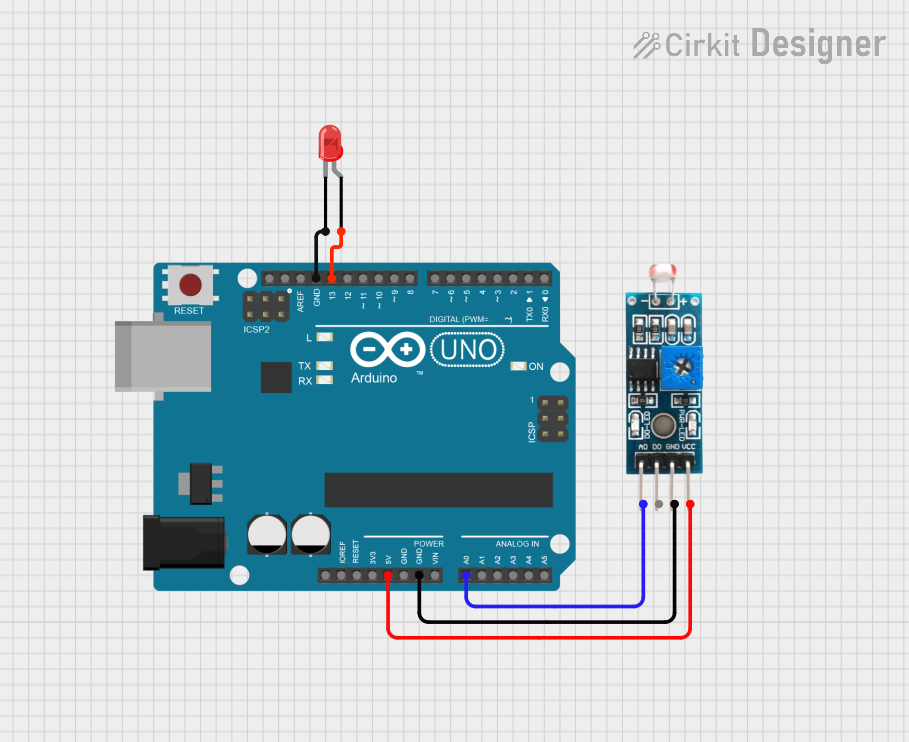
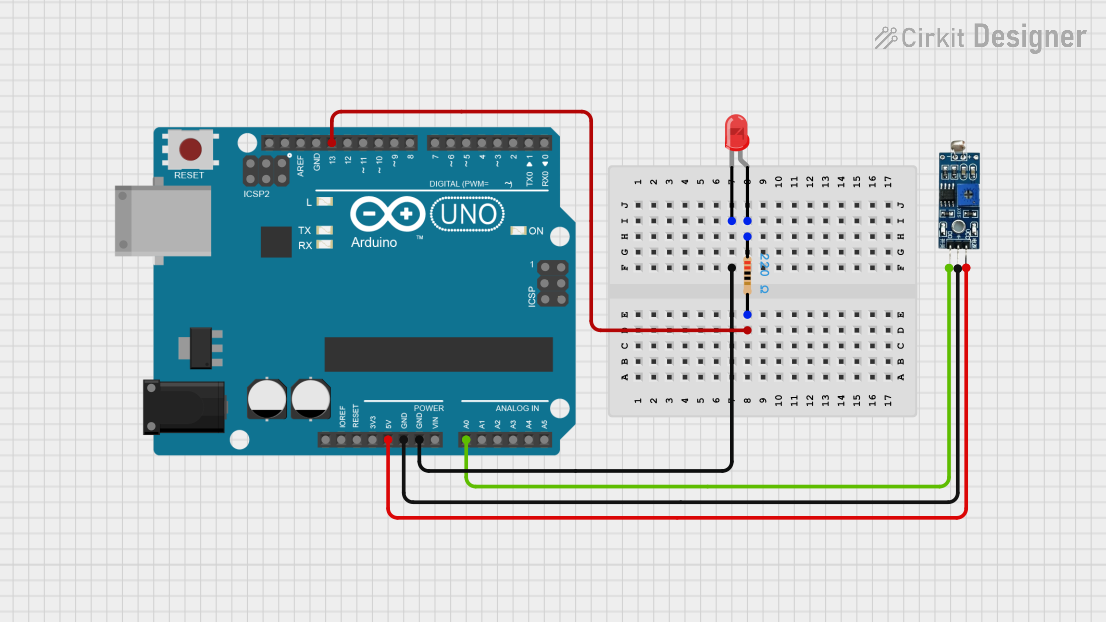
How to Use the Component in a Circuit

  1. Connect the VCC pin to a 3.3V or 5V power supply.
  2. Connect the GND pin to the ground of the power supply.
  3. Connect the Signal Output to an analog input pin on a microcontroller, such as an Arduino UNO.

Important Considerations and Best Practices

  • Avoid exposing the LDR to extreme light intensities that may exceed its maximum voltage rating.
  • Shield the LDR from artificial light sources when measuring natural light to avoid skewed readings.
  • Use a pull-down resistor if the microcontroller analog input pin has a high impedance.

Example Code for Arduino UNO

// Define the LDR pin
const int ldrPin = A0;

void setup() {
  // Initialize serial communication at 9600 bits per second:
  Serial.begin(9600);
}

void loop() {
  // Read the input on analog pin 0:
  int sensorValue = analogRead(ldrPin);
  // Convert the analog reading (which goes from 0 - 1023) to a voltage (0 - 5V):
  float voltage = sensorValue * (5.0 / 1023.0);
  // Print out the value you read:
  Serial.println(voltage);
  delay(1000); // Delay in between reads for stability
}

Troubleshooting and FAQs

Common Issues Users Might Face

  • Inconsistent Readings: Ensure that the LDR is not subjected to fluctuating light conditions and that it is properly connected to the analog input.
  • No Readings: Check the power supply connections and ensure that the LDR module is not damaged.

Solutions and Tips for Troubleshooting

  • If the readings are erratic, consider adding a capacitor across the power and ground pins to stabilize the power supply.
  • Use a multimeter to check the continuity of the LDR and ensure that there are no breaks in the circuit.

FAQs

Q: Can I use the LDR module with a 3.3V system? A: Yes, the LDR module can be used with both 3.3V and 5V systems.

Q: What is the sensitivity range of the LDR module? A: The LDR module is most sensitive to light around 540 nm, which is in the visible light spectrum.

Q: How do I calibrate the LDR module for accurate light measurements? A: Calibration involves recording the LDR response at known light intensities and creating a reference curve or table to interpret future readings accurately.

This documentation provides a comprehensive guide to using the LDR module in electronic projects. For further assistance, consult the manufacturer's datasheet or contact technical support.