Cirkit Designer Logo
Cirkit Designer
Your all-in-one circuit design IDE
Home / 
Component Documentation

How to Use PCF: Examples, Pinouts, and Specs

Image of PCF
Cirkit Designer LogoDesign with PCF in Cirkit Designer

Introduction

The PCF (Programmable Clock Frequency) is a versatile electronic component designed to generate precise clock signals. These signals are essential for synchronizing various components in digital systems, ensuring accurate timing and coordination. The PCF is widely used in applications such as microcontroller-based systems, communication devices, and digital signal processing.

Explore Projects Built with PCF

Use Cirkit Designer to design, explore, and prototype these projects online. Some projects support real-time simulation. Click "Open Project" to start designing instantly!
Biometric and RFID Security System with Dual Adafruit Feather nRF52840 Controllers
Image of Rfid access control: A project utilizing PCF in a practical application
This circuit features two Adafruit Feather nRF52840 microcontrollers, each interfaced with an RFID-RC522 module for RFID communication and an AT24C256 external EEPROM for additional memory storage. One of the microcontrollers is also connected to an R307 Fingerprint Sensor for biometric input, and both microcontrollers are powered by a shared power supply and a coin cell breakout for backup or RTC power. The circuit is likely designed for secure access control or identification purposes, utilizing both RFID and fingerprint authentication, with data storage capabilities.
Cirkit Designer LogoOpen Project in Cirkit Designer
Raspberry Pi Pico W-Based Multi-Sensor Security System
Image of 300DT: A project utilizing PCF in a practical application
This circuit is designed for a security system that detects fire, sound, light changes, movement, and IR triggers using a Raspberry Pi Pico W as the central microcontroller. It includes a flame sensor, sound sensor (KY-038), LDR photoresistor, ultrasonic sensor, IR sensor, and a piezo speaker for alerts. The system monitors the environment for any disturbances and alerts personnel through the piezo speaker when an anomaly is detected.
Cirkit Designer LogoOpen Project in Cirkit Designer
Arduino UNO-Based Real-Time Clock with I2C LCD Display and IO Expansion
Image of teste: A project utilizing PCF in a practical application
This circuit is an Arduino-based real-time clock and display system. It uses an Arduino UNO to interface with a DS1307 RTC module for timekeeping and a 20x4 I2C LCD to display the current time and date. Additionally, a PCF8574 IO Expansion Board is used to extend the I2C bus for additional I/O operations.
Cirkit Designer LogoOpen Project in Cirkit Designer
ESP32-Based Security System with RFID, PIR Sensor, and Laser Detection
Image of doorlock: A project utilizing PCF in a practical application
This circuit features an ESP32 microcontroller as the central processing unit, interfaced with a variety of sensors and modules. It includes a PIR sensor for motion detection, an RFID-RC522 module for RFID communication, a 4x4 membrane matrix keypad for user input, and an ESP32-CAM module for capturing images or video. Additionally, the circuit uses a PCF8575 I/O expander to increase the number of available I/O pins, a KY-008 laser emitter, and a corresponding laser receiver module to detect laser beam interruptions.
Cirkit Designer LogoOpen Project in Cirkit Designer

Explore Projects Built with PCF

Use Cirkit Designer to design, explore, and prototype these projects online. Some projects support real-time simulation. Click "Open Project" to start designing instantly!
Image of Rfid access control: A project utilizing PCF in a practical application
Biometric and RFID Security System with Dual Adafruit Feather nRF52840 Controllers
This circuit features two Adafruit Feather nRF52840 microcontrollers, each interfaced with an RFID-RC522 module for RFID communication and an AT24C256 external EEPROM for additional memory storage. One of the microcontrollers is also connected to an R307 Fingerprint Sensor for biometric input, and both microcontrollers are powered by a shared power supply and a coin cell breakout for backup or RTC power. The circuit is likely designed for secure access control or identification purposes, utilizing both RFID and fingerprint authentication, with data storage capabilities.
Cirkit Designer LogoOpen Project in Cirkit Designer
Image of 300DT: A project utilizing PCF in a practical application
Raspberry Pi Pico W-Based Multi-Sensor Security System
This circuit is designed for a security system that detects fire, sound, light changes, movement, and IR triggers using a Raspberry Pi Pico W as the central microcontroller. It includes a flame sensor, sound sensor (KY-038), LDR photoresistor, ultrasonic sensor, IR sensor, and a piezo speaker for alerts. The system monitors the environment for any disturbances and alerts personnel through the piezo speaker when an anomaly is detected.
Cirkit Designer LogoOpen Project in Cirkit Designer
Image of teste: A project utilizing PCF in a practical application
Arduino UNO-Based Real-Time Clock with I2C LCD Display and IO Expansion
This circuit is an Arduino-based real-time clock and display system. It uses an Arduino UNO to interface with a DS1307 RTC module for timekeeping and a 20x4 I2C LCD to display the current time and date. Additionally, a PCF8574 IO Expansion Board is used to extend the I2C bus for additional I/O operations.
Cirkit Designer LogoOpen Project in Cirkit Designer
Image of doorlock: A project utilizing PCF in a practical application
ESP32-Based Security System with RFID, PIR Sensor, and Laser Detection
This circuit features an ESP32 microcontroller as the central processing unit, interfaced with a variety of sensors and modules. It includes a PIR sensor for motion detection, an RFID-RC522 module for RFID communication, a 4x4 membrane matrix keypad for user input, and an ESP32-CAM module for capturing images or video. Additionally, the circuit uses a PCF8575 I/O expander to increase the number of available I/O pins, a KY-008 laser emitter, and a corresponding laser receiver module to detect laser beam interruptions.
Cirkit Designer LogoOpen Project in Cirkit Designer

Common Applications and Use Cases

  • Microcontroller clock generation
  • Synchronization in communication systems
  • Timing control in digital signal processing
  • Frequency generation for testing and measurement equipment
  • Clock signal distribution in embedded systems

Technical Specifications

The PCF is a highly configurable component with the following key specifications:

Key Technical Details

  • Operating Voltage: 2.7V to 5.5V
  • Frequency Range: 1 Hz to 40 MHz (programmable)
  • Output Signal Type: Square wave
  • Output Voltage Levels: TTL-compatible
  • Power Consumption: Low-power operation, typically <10 mW
  • Temperature Range: -40°C to +85°C
  • Communication Interface: I2C or SPI (depending on the model)

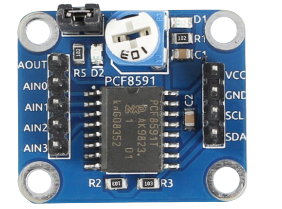
Pin Configuration and Descriptions

The PCF typically comes in an 8-pin package. Below is the pinout description:

Pin Number Pin Name Description
1 VCC Power supply input (2.7V to 5.5V)
2 GND Ground
3 SCL Serial Clock Line for I2C communication
4 SDA Serial Data Line for I2C communication
5 OUT Clock signal output
6 NC No connection (leave unconnected)
7 CONFIG Configuration pin for frequency programming
8 ENABLE Enable/disable the clock output

Usage Instructions

How to Use the PCF in a Circuit

  1. Power Supply: Connect the VCC pin to a stable power source (2.7V to 5.5V) and the GND pin to ground.
  2. Communication Interface: Use the SCL and SDA pins to communicate with the PCF via the I2C protocol. Ensure proper pull-up resistors (typically 4.7kΩ) are connected to these lines.
  3. Frequency Configuration: Program the desired clock frequency using the CONFIG pin or through I2C commands.
  4. Clock Output: Connect the OUT pin to the component or system requiring the clock signal.
  5. Enable/Disable: Use the ENABLE pin to turn the clock output on or off as needed.

Important Considerations and Best Practices

  • Decoupling Capacitors: Place a 0.1 µF ceramic capacitor close to the VCC pin to filter noise and ensure stable operation.
  • Signal Integrity: Keep the clock output trace as short as possible to minimize signal degradation.
  • Pull-up Resistors: Ensure proper pull-up resistors are used on the I2C lines for reliable communication.
  • Programming: Refer to the PCF datasheet for detailed instructions on programming the frequency via I2C commands.

Example: Using PCF with Arduino UNO

Below is an example of how to use the PCF with an Arduino UNO to generate a 1 MHz clock signal:

#include <Wire.h> // Include the Wire library for I2C communication

#define PCF_I2C_ADDRESS 0x60 // Replace with the actual I2C address of your PCF

void setup() {
  Wire.begin(); // Initialize I2C communication
  Serial.begin(9600); // Initialize serial communication for debugging

  // Configure the PCF to output a 1 MHz clock signal
  Wire.beginTransmission(PCF_I2C_ADDRESS);
  Wire.write(0x00); // Register address for frequency configuration
  Wire.write(0x10); // Example value to set 1 MHz (refer to datasheet for details)
  Wire.endTransmission();

  Serial.println("PCF configured to output 1 MHz clock signal.");
}

void loop() {
  // The PCF will continuously output the configured clock signal
}

Troubleshooting and FAQs

Common Issues and Solutions

  1. No Clock Output:

    • Ensure the ENABLE pin is set to the correct state (high or low, depending on the model).
    • Verify the power supply voltage is within the specified range.
    • Check the I2C communication for errors (e.g., incorrect address or missing pull-up resistors).
  2. Incorrect Frequency Output:

    • Double-check the frequency configuration settings.
    • Refer to the PCF datasheet for the correct register values for the desired frequency.
  3. I2C Communication Failure:

    • Ensure proper pull-up resistors (4.7kΩ) are connected to the SCL and SDA lines.
    • Verify the I2C address of the PCF matches the address used in the code.

FAQs

Q: Can the PCF generate multiple clock signals simultaneously?
A: No, the PCF typically generates a single clock signal. For multiple signals, use additional PCF components or a clock distribution IC.

Q: What is the maximum clock frequency the PCF can generate?
A: The PCF can generate clock signals up to 40 MHz, depending on the model.

Q: Is the PCF compatible with 3.3V systems?
A: Yes, the PCF operates within a voltage range of 2.7V to 5.5V, making it compatible with both 3.3V and 5V systems.

Q: How do I calculate the register values for a specific frequency?
A: Refer to the PCF datasheet for the formula or lookup table to calculate the register values for the desired frequency.