
How to Use ESC1: Examples, Pinouts, and Specs
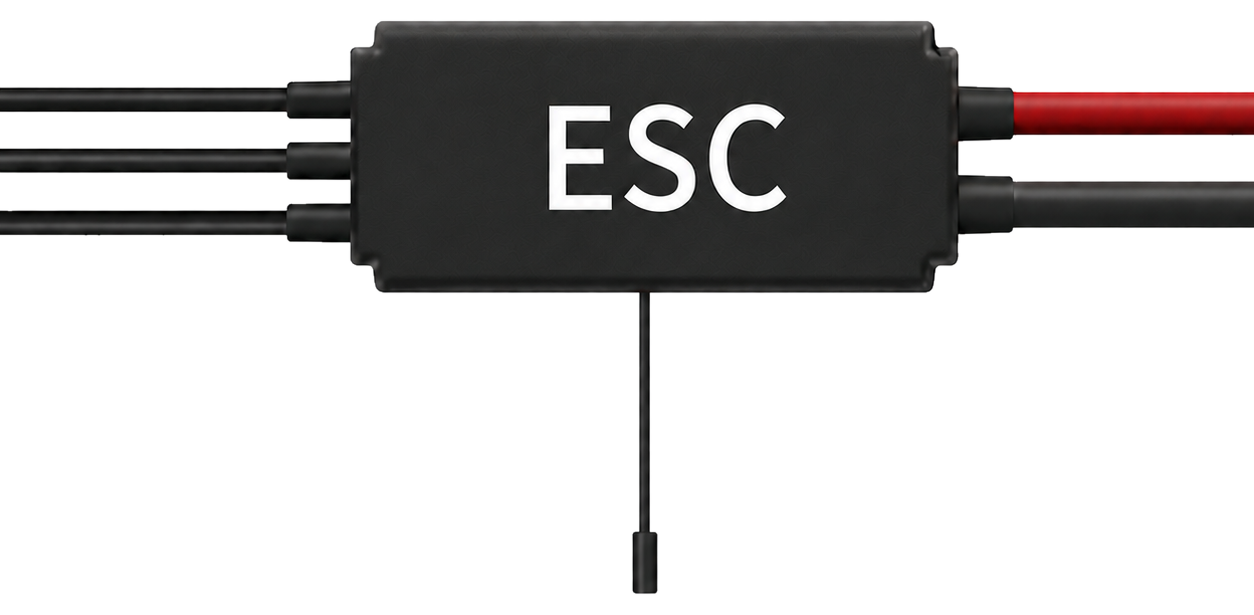
 Design with ESC1 in Cirkit Designer
Introduction
An Electronic Speed Controller (ESC) is a critical component used to regulate the speed, direction, and braking of an electric motor. The ESC1 is specifically designed for brushless DC motors, making it ideal for applications such as remote-controlled vehicles, drones, and robotics. By adjusting the power supplied to the motor, the ESC1 ensures smooth and precise control over motor performance.
Explore Projects Built with ESC1
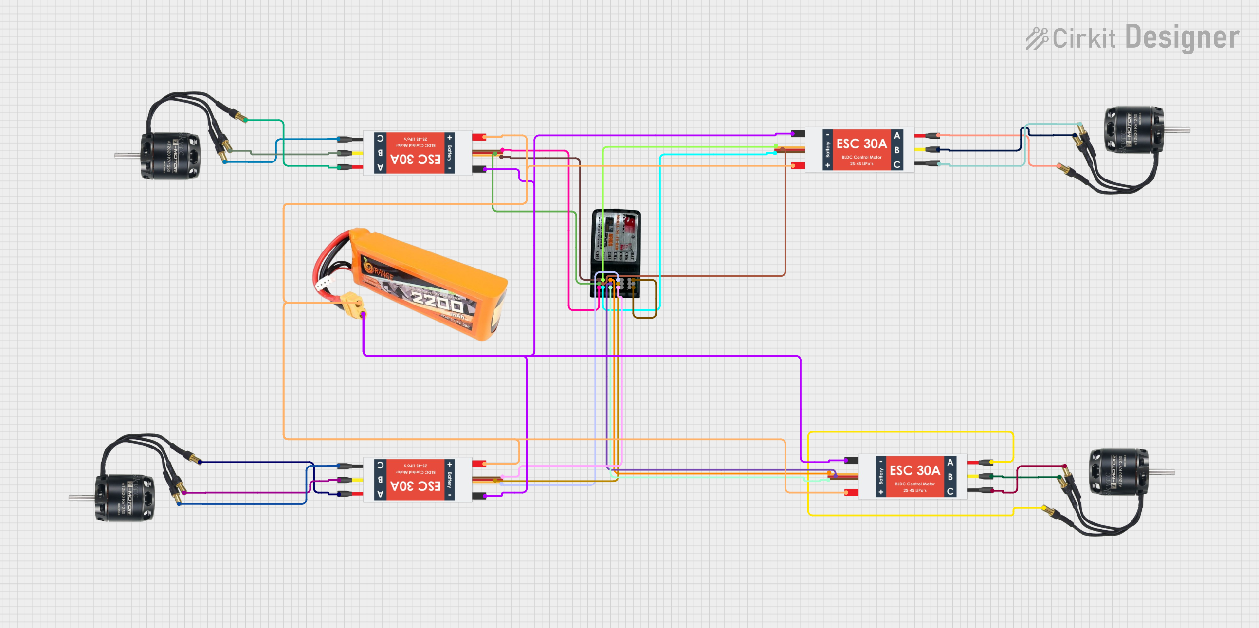 Open Project in Cirkit Designer
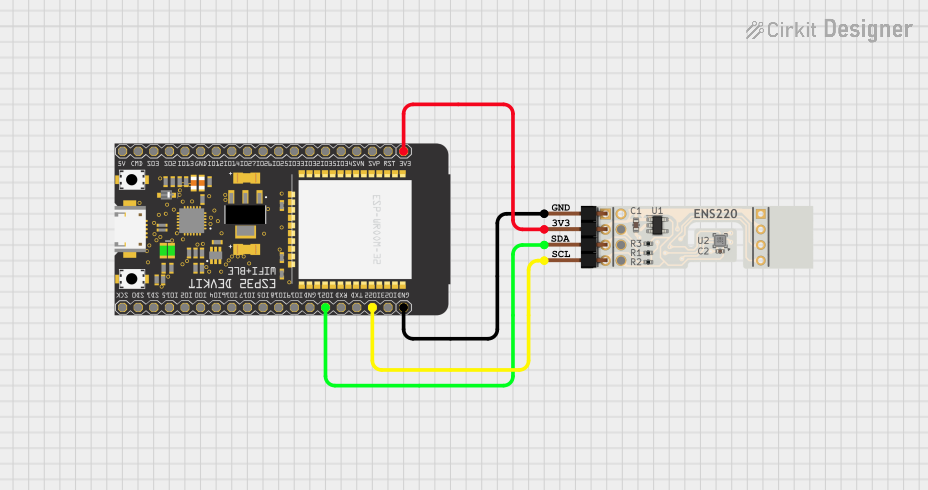 Open Project in Cirkit Designer
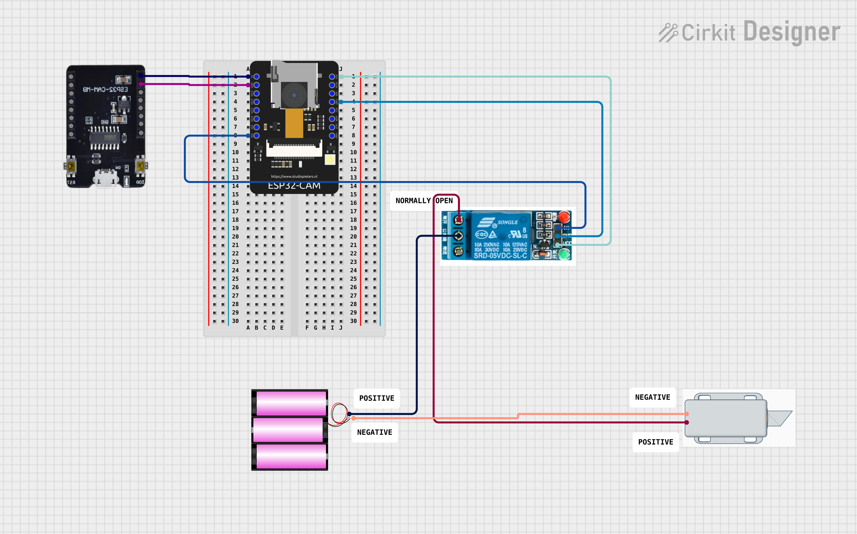 Open Project in Cirkit Designer
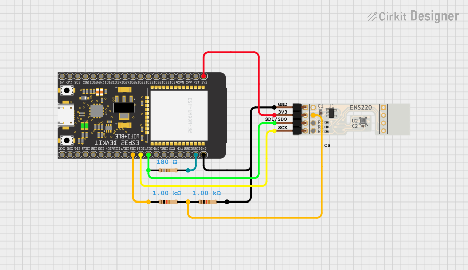 Open Project in Cirkit Designer
Explore Projects Built with ESC1
Open Project in Cirkit DesignerOpen Project in Cirkit DesignerOpen Project in Cirkit DesignerOpen Project in Cirkit DesignerCommon Applications and Use Cases
- Remote-controlled cars, boats, and airplanes
- Drones and quadcopters
- Robotics and automation systems
- Electric bicycles and scooters
- Industrial motor control systems
Technical Specifications
The ESC1 is designed to provide reliable and efficient motor control. Below are its key technical specifications:
| Parameter | Value |
|---|---|
| Input Voltage Range | 6V to 24V (2S to 6S LiPo batteries) |
| Continuous Current | 30A |
| Peak Current | 40A (for up to 10 seconds) |
| Motor Compatibility | Brushless DC motors |
| Signal Input | PWM (Pulse Width Modulation) |
| PWM Frequency Range | 50Hz to 500Hz |
| BEC Output | 5V, 2A (Battery Eliminator Circuit) |
| Operating Temperature | -10°C to 60°C |
| Dimensions | 45mm x 25mm x 10mm |
| Weight | 25g |
Pin Configuration and Descriptions
The ESC1 has three main connection points: motor wires, power input, and signal input. Below is the pin configuration:
| Pin/Connection | Description |
|---|---|
| Motor Wires (A, B, C) | Connect to the three-phase brushless motor terminals. |
| Power Input (+, -) | Connect to the battery (observe polarity). |
| Signal Input (PWM) | Receives control signals from a microcontroller or receiver. |
| BEC Output (+, -) | Provides 5V power for external devices like a receiver or microcontroller. |
Usage Instructions
How to Use the ESC1 in a Circuit
- Connect the Motor: Attach the three motor wires (A, B, C) from the ESC1 to the brushless motor terminals. If the motor spins in the wrong direction, swap any two wires.
- Connect the Power Source: Connect the battery to the power input terminals of the ESC1. Ensure correct polarity to avoid damage.
- Connect the Signal Input: Use a PWM signal from a microcontroller (e.g., Arduino UNO) or a receiver to control the ESC1.
- Optional BEC Connection: If needed, use the BEC output to power external devices like a microcontroller or receiver.
Important Considerations and Best Practices
- Battery Compatibility: Ensure the battery voltage is within the ESC1's input voltage range (6V to 24V).
- Cooling: Avoid overheating by ensuring proper ventilation or adding a heatsink if necessary.
- Signal Calibration: Calibrate the ESC1 with your transmitter or microcontroller to ensure accurate control.
- Startup Safety: Always ensure the motor is securely mounted and the propeller (if applicable) is removed during initial setup.
Example Code for Arduino UNO
Below is an example of how to control the ESC1 using an Arduino UNO:
#include <Servo.h> // Include the Servo library for PWM signal generation

Servo esc; // Create a Servo object to control the ESC

void setup() {
  esc.attach(9); // Attach the ESC signal wire to pin 9 on the Arduino
  esc.writeMicroseconds(1000); // Send minimum throttle signal (1000 µs)
  delay(2000); // Wait for 2 seconds to allow ESC initialization
}

void loop() {
  esc.writeMicroseconds(1500); // Set throttle to 50% (1500 µs)
  delay(5000); // Run motor at 50% throttle for 5 seconds

  esc.writeMicroseconds(1000); // Set throttle to 0% (1000 µs)
  delay(5000); // Stop motor for 5 seconds
}
Note: Adjust the throttle values (1000 to 2000 microseconds) based on your motor and ESC calibration.
Troubleshooting and FAQs
Common Issues and Solutions
Motor Does Not Spin:
- Cause: Incorrect wiring or no signal input.
- Solution: Verify motor connections and ensure the PWM signal is being sent correctly.
Motor Spins in the Wrong Direction:
- Cause: Incorrect motor wire connections.
- Solution: Swap any two motor wires (A, B, or C).
ESC Overheats:
- Cause: Excessive current draw or poor ventilation.
- Solution: Ensure the motor is not overloaded and improve cooling.
No Power Output from BEC:
- Cause: Faulty BEC circuit or incorrect wiring.
- Solution: Check the BEC output connections and measure the voltage with a multimeter.
ESC Beeps Continuously:
- Cause: No signal input or low battery voltage.
- Solution: Verify the PWM signal and ensure the battery is charged.
FAQs
Q: Can the ESC1 be used with brushed motors?
A: No, the ESC1 is designed specifically for brushless DC motors.Q: What happens if I exceed the input voltage range?
A: Exceeding the voltage range may permanently damage the ESC1. Always use a compatible battery.Q: How do I calibrate the ESC1 with my transmitter?
A: Follow the ESC1's calibration procedure, typically involving setting the throttle to maximum and minimum positions during initialization.Q: Can I use the ESC1 without a BEC?
A: Yes, but you will need an external power source for devices like the receiver or microcontroller.
By following this documentation, you can effectively integrate the ESC1 into your projects and troubleshoot common issues with ease.