How to Use IR2104: Examples, Pinouts, and Specs
Introduction
The IR2104 is a high and low side driver IC designed to drive N-channel MOSFETs and IGBTs in half-bridge and full-bridge configurations. It is widely used in motor control, power conversion, and other high-voltage applications. The IR2104 features a high voltage capability of up to 600V, built-in dead time control to prevent shoot-through, and a compact design that simplifies circuit implementation.
Explore Projects Built with IR2104
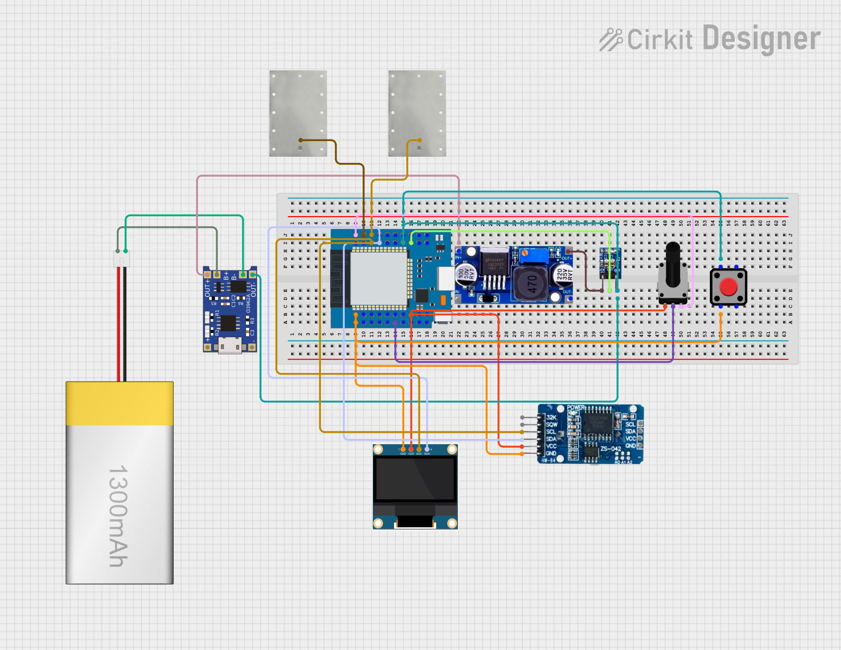
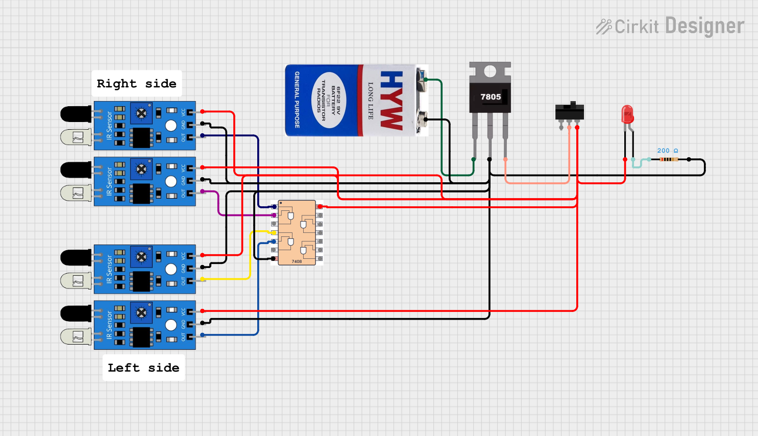
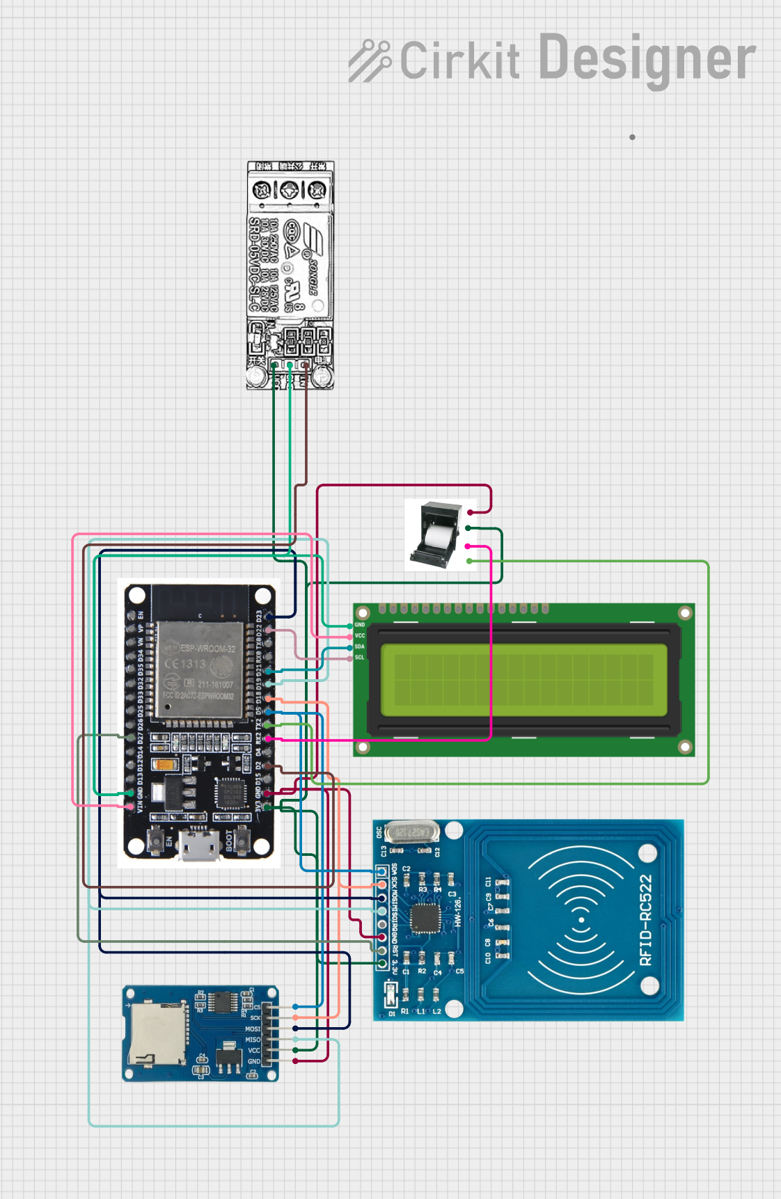

Explore Projects Built with IR2104
Common Applications
- Motor control systems (e.g., BLDC and stepper motors)
- DC-DC and AC-DC power converters
- Uninterruptible Power Supplies (UPS)
- Solar inverters
- Industrial automation systems
Technical Specifications
Key Technical Details
| Parameter | Value |
|---|---|
| High-Side Floating Voltage (VB) | Up to 600V |
| Gate Drive Voltage (VCC) | 10V to 20V |
| Logic Input Voltage (VIN) | 0V to 5V |
| Dead Time Control | Built-in (typical 520ns) |
| Output Current (Source) | 130mA |
| Output Current (Sink) | 270mA |
| Propagation Delay | 120ns (typical) |
| Operating Temperature | -40°C to +125°C |
| Package Type | DIP-8, SOIC-8 |
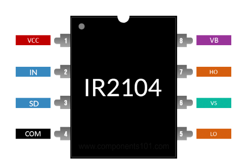
Pin Configuration and Descriptions
The IR2104 is an 8-pin IC. Below is the pinout and description:
| Pin No. | Pin Name | Description |
|---|---|---|
| 1 | VCC | Low-side and logic fixed supply voltage (10V to 20V). |
| 2 | IN | Logic input for controlling the high-side and low-side outputs. |
| 3 | SD | Shutdown input (active low). Disables both high-side and low-side outputs. |
| 4 | COM | Ground reference for the low-side driver and logic. |
| 5 | LO | Low-side output for driving the low-side MOSFET/IGBT. |
| 6 | VS | High-side floating supply return. Connects to the source of the high-side MOSFET. |
| 7 | HO | High-side output for driving the high-side MOSFET/IGBT. |
| 8 | VB | High-side floating supply voltage. |
Usage Instructions
How to Use the IR2104 in a Circuit
- Power Supply: Connect VCC to a stable 10V-20V power supply. Ensure proper decoupling with a capacitor (e.g., 0.1µF ceramic capacitor) close to the VCC pin.
- Logic Inputs: Drive the IN pin with a 0V-5V logic signal to control the high-side and low-side outputs. Use the SD pin to enable or disable the driver (active low).
- High-Side Floating Supply: Connect VB to a bootstrap circuit (diode and capacitor) to provide the necessary voltage for the high-side driver.
- MOSFET/IGBT Connections: Connect the HO pin to the gate of the high-side MOSFET/IGBT and the LO pin to the gate of the low-side MOSFET/IGBT.
- Grounding: Ensure a solid ground connection at the COM pin for proper operation.
Important Considerations
- Bootstrap Circuit: Use a fast recovery diode (e.g., UF4007) and a bootstrap capacitor (e.g., 0.1µF to 1µF) to ensure proper high-side operation.
- Dead Time: The IR2104 has a built-in dead time to prevent shoot-through. Avoid adding external dead time unless necessary.
- Voltage Ratings: Ensure that the high-side floating voltage (VB) does not exceed 600V.
- Heat Dissipation: If operating at high frequencies or driving large MOSFETs, ensure proper heat dissipation for the IC.
Example: Using IR2104 with Arduino UNO
Below is an example of how to control the IR2104 using an Arduino UNO to drive a half-bridge circuit:
// Example: Controlling IR2104 with Arduino UNO
// Connect IN pin of IR2104 to Arduino pin 9
// Connect SD pin of IR2104 to Arduino pin 8

#define IN_PIN 9  // Arduino pin connected to IR2104 IN pin
#define SD_PIN 8  // Arduino pin connected to IR2104 SD pin

void setup() {
  pinMode(IN_PIN, OUTPUT);  // Set IN pin as output
  pinMode(SD_PIN, OUTPUT);  // Set SD pin as output

  digitalWrite(SD_PIN, HIGH);  // Enable the IR2104 driver
}

void loop() {
  digitalWrite(IN_PIN, HIGH);  // Turn on high-side MOSFET
  delay(1000);                 // Wait for 1 second
  digitalWrite(IN_PIN, LOW);   // Turn on low-side MOSFET
  delay(1000);                 // Wait for 1 second
}
Notes:
- Ensure proper connections between the Arduino, IR2104, and the MOSFETs.
- Use appropriate pull-down resistors on the IN and SD pins to avoid floating inputs.
Troubleshooting and FAQs
Common Issues and Solutions
No Output on HO or LO Pins:
- Check the VCC supply voltage (should be between 10V and 20V).
- Verify that the SD pin is set to HIGH (logic 1) to enable the driver.
- Ensure proper bootstrap circuit connections for the high-side driver.
High-Side MOSFET Not Turning On:
- Verify the bootstrap capacitor and diode are functioning correctly.
- Check that the VB voltage is sufficiently higher than the source voltage of the high-side MOSFET.
Overheating of the IR2104:
- Ensure the IC is not driving MOSFETs with excessive gate capacitance at high frequencies.
- Add a heatsink or improve ventilation if necessary.
Shoot-Through in the MOSFETs:
- Verify that the dead time is sufficient to prevent simultaneous conduction of high-side and low-side MOSFETs.
- Avoid external circuitry that interferes with the IR2104's built-in dead time.
FAQs
Q1: Can the IR2104 drive P-channel MOSFETs?
A1: No, the IR2104 is specifically designed for N-channel MOSFETs and IGBTs.
Q2: What is the maximum switching frequency of the IR2104?
A2: The maximum switching frequency depends on the load and gate capacitance of the MOSFETs. Typically, it can operate up to 500kHz with proper design.
Q3: Can I use the IR2104 for a full-bridge configuration?
A3: Yes, you can use two IR2104 ICs to drive a full-bridge circuit.
Q4: Is the IR2104 suitable for low-voltage applications?
A4: The IR2104 is optimized for high-voltage applications. For low-voltage designs, consider using a dedicated low-voltage gate driver.
Q5: Do I need external dead time control?
A5: The IR2104 has a built-in dead time, so external dead time control is generally not required.