
How to Use BMS 12.8V 50A 4S LiFePO4 LFP : Examples, Pinouts, and Specs
 Design with BMS 12.8V 50A 4S LiFePO4 LFP in Cirkit Designer
Introduction
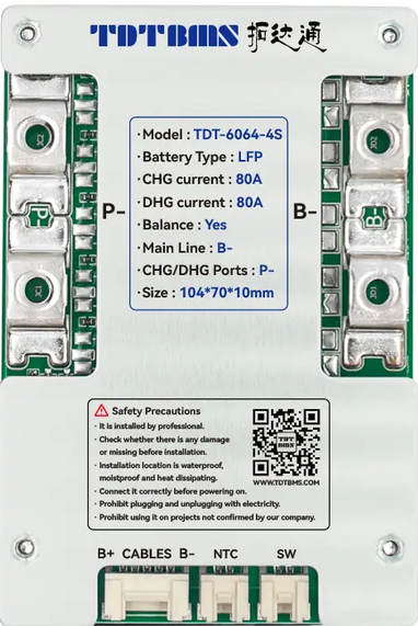
The TDTBMS 6064 4S is a Battery Management System (BMS) specifically designed for 12.8V lithium iron phosphate (LiFePO4) battery packs. It is capable of managing up to 50A of current, making it suitable for high-power applications. This BMS ensures the safety, longevity, and optimal performance of a 4-cell series (4S) LiFePO4 battery pack by monitoring critical parameters such as voltage, current, and temperature.
Explore Projects Built with BMS 12.8V 50A 4S LiFePO4 LFP
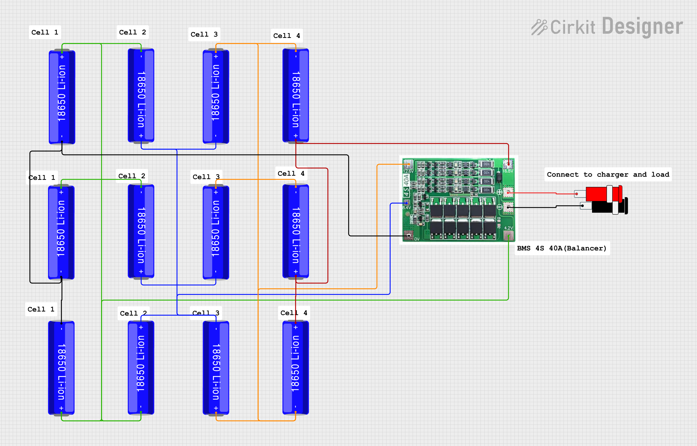 Open Project in Cirkit Designer
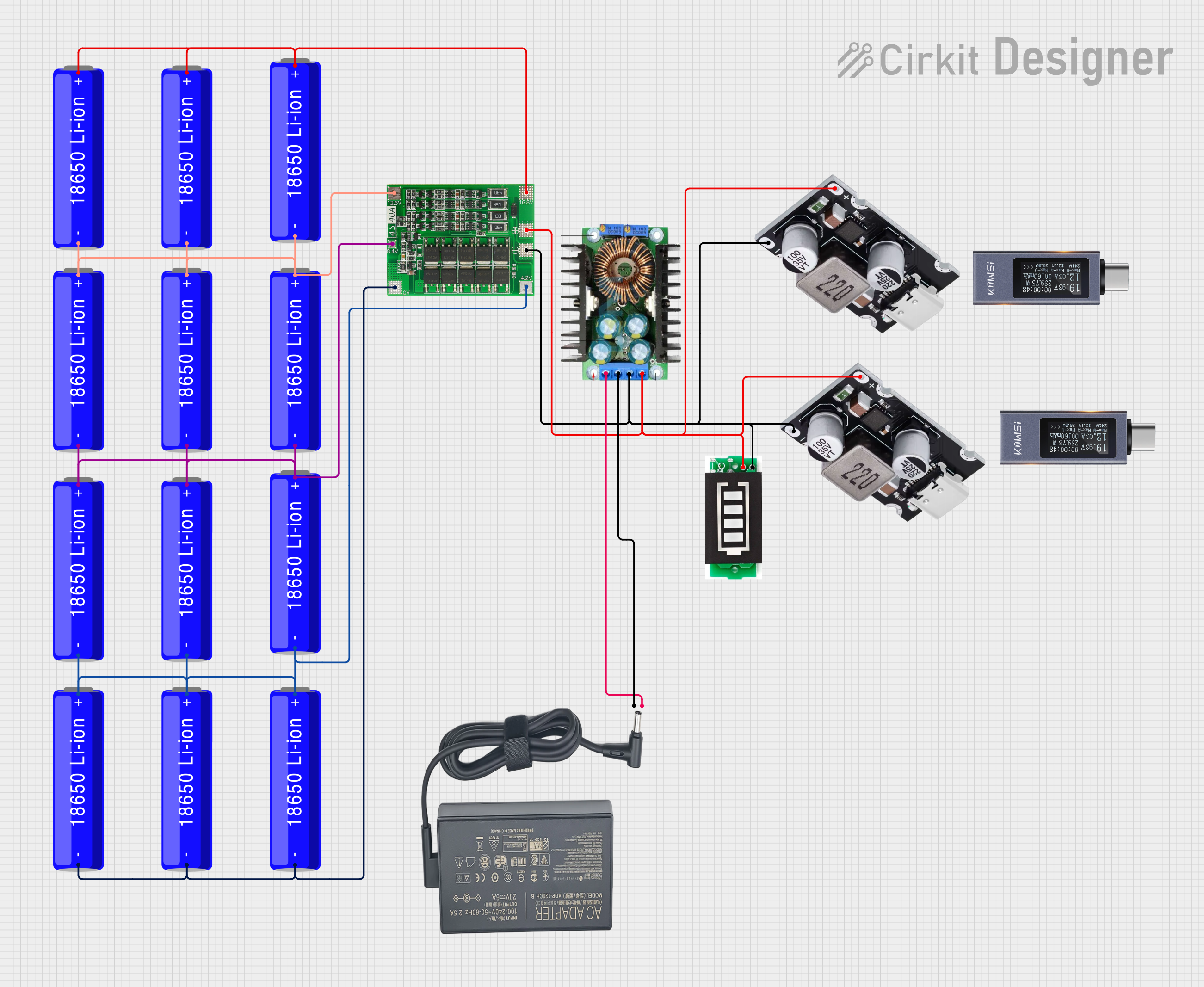 Open Project in Cirkit Designer
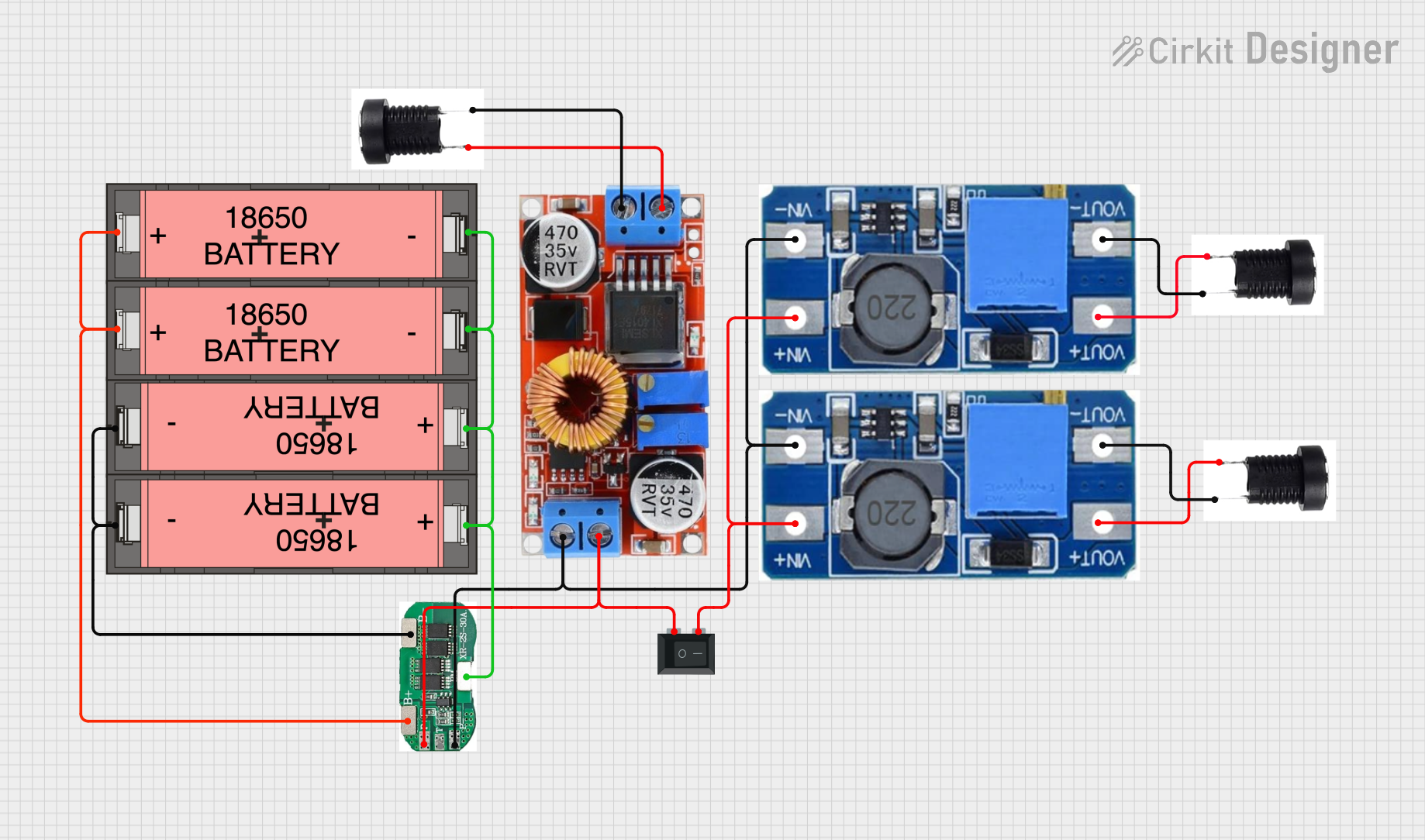 Open Project in Cirkit Designer
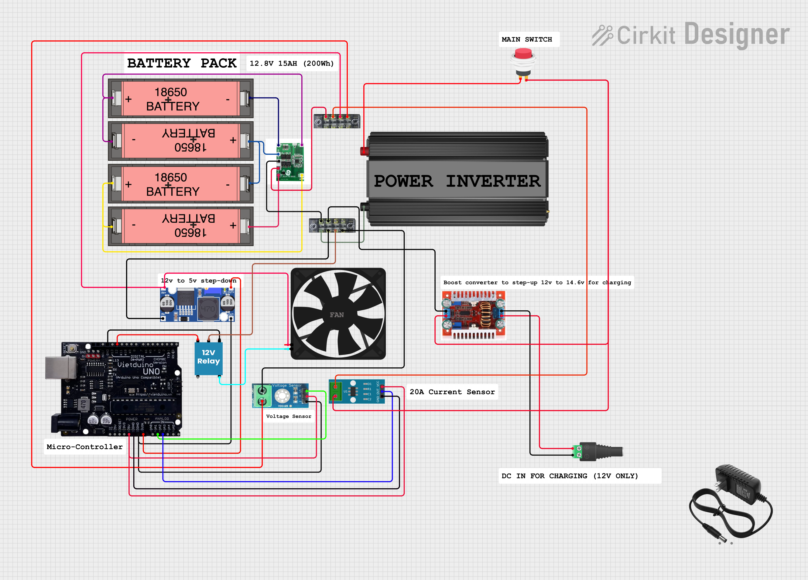 Open Project in Cirkit Designer
Explore Projects Built with BMS 12.8V 50A 4S LiFePO4 LFP
Open Project in Cirkit DesignerOpen Project in Cirkit DesignerOpen Project in Cirkit DesignerOpen Project in Cirkit DesignerCommon Applications
- Solar energy storage systems
- Electric bicycles and scooters
- Uninterruptible Power Supplies (UPS)
- Portable power stations
- Robotics and industrial equipment
Technical Specifications
Key Specifications
| Parameter | Value |
|---|---|
| Nominal Battery Voltage | 12.8V |
| Supported Battery Type | LiFePO4 (Lithium Iron Phosphate) |
| Maximum Continuous Current | 50A |
| Overcharge Protection | 3.65V ± 0.05V per cell |
| Overdischarge Protection | 2.5V ± 0.05V per cell |
| Balance Current | 50mA |
| Operating Temperature | -20°C to 60°C |
| Dimensions | 65mm x 45mm x 10mm |
| Manufacturer Part ID | 6064 4S |
Pin Configuration and Descriptions
The BMS has multiple connection points for battery cells, load, and charger. Below is the pin configuration:
| Pin Name | Description |
|---|---|
| B- | Battery negative terminal (connect to the negative terminal of the battery pack) |
| B1 | Positive terminal of Cell 1 |
| B2 | Positive terminal of Cell 2 |
| B3 | Positive terminal of Cell 3 |
| B4 | Positive terminal of Cell 4 |
| P- | Power negative terminal (connect to the load and charger negative terminal) |
| C- | Charger negative terminal (optional, for separate charging circuit) |
Usage Instructions
How to Use the BMS in a Circuit
Connect the Battery Pack:
- Connect the negative terminal of the battery pack to the B- pin.
- Connect the positive terminals of each cell to the corresponding pins (B1, B2, B3, B4) in sequence.
- Ensure all connections are secure and properly insulated to avoid short circuits.
Connect the Load:
- Connect the negative terminal of the load to the P- pin.
- The positive terminal of the load should connect directly to the positive terminal of the battery pack.
Connect the Charger:
- If using a separate charging circuit, connect the negative terminal of the charger to the C- pin.
- The positive terminal of the charger should connect directly to the positive terminal of the battery pack.
Verify Connections:
- Double-check all connections to ensure they are correct and secure.
- Use a multimeter to verify the voltage across the battery pack and individual cells.
Power On:
- Once all connections are verified, power on the system. The BMS will automatically manage charging, discharging, and balancing.
Important Considerations and Best Practices
- Cell Matching: Ensure all cells in the battery pack are of the same capacity, voltage, and internal resistance to avoid imbalance.
- Heat Dissipation: Install the BMS in a well-ventilated area or use a heatsink if operating near the maximum current rating.
- Avoid Overloading: Do not exceed the 50A current limit to prevent damage to the BMS.
- Wiring: Use appropriately rated wires for the current to minimize resistance and heat generation.
- Testing: Test the BMS with a small load before connecting it to the full system.
Arduino Integration Example
The BMS can be monitored using an Arduino by measuring the voltage of each cell. Below is an example code snippet for reading cell voltages using analog inputs:
// Example code to monitor cell voltages using Arduino
// Ensure proper voltage dividers are used to scale down cell voltages
// to within the Arduino's ADC input range (0-5V).

const int cell1Pin = A0; // Analog pin for Cell 1
const int cell2Pin = A1; // Analog pin for Cell 2
const int cell3Pin = A2; // Analog pin for Cell 3
const int cell4Pin = A3; // Analog pin for Cell 4

void setup() {
  Serial.begin(9600); // Initialize serial communication
}

void loop() {
  // Read cell voltages (scaled by voltage dividers)
  float cell1Voltage = analogRead(cell1Pin) * (5.0 / 1023.0) * 4.0; // Adjust scale factor
  float cell2Voltage = analogRead(cell2Pin) * (5.0 / 1023.0) * 4.0;
  float cell3Voltage = analogRead(cell3Pin) * (5.0 / 1023.0) * 4.0;
  float cell4Voltage = analogRead(cell4Pin) * (5.0 / 1023.0) * 4.0;

  // Print voltages to Serial Monitor
  Serial.print("Cell 1 Voltage: ");
  Serial.println(cell1Voltage);
  Serial.print("Cell 2 Voltage: ");
  Serial.println(cell2Voltage);
  Serial.print("Cell 3 Voltage: ");
  Serial.println(cell3Voltage);
  Serial.print("Cell 4 Voltage: ");
  Serial.println(cell4Voltage);

  delay(1000); // Wait 1 second before next reading
}
Troubleshooting and FAQs
Common Issues and Solutions
BMS Not Powering On:
- Cause: Incorrect wiring or loose connections.
- Solution: Verify all connections, especially the battery terminals and balance leads.
Overheating:
- Cause: Exceeding the maximum current rating or poor ventilation.
- Solution: Reduce the load current or improve heat dissipation with a heatsink or fan.
Uneven Cell Voltages:
- Cause: Cells are not balanced or have different capacities.
- Solution: Allow the BMS to balance the cells over time or manually balance the cells before connecting to the BMS.
Charger Not Working:
- Cause: Charger voltage is too high or too low.
- Solution: Use a charger with a voltage range suitable for a 12.8V LiFePO4 battery pack.
FAQs
Can this BMS be used with other battery chemistries? No, this BMS is specifically designed for LiFePO4 batteries and should not be used with other chemistries.
What happens if one cell fails? The BMS will detect the failure and may shut down to prevent further damage. Replace the faulty cell immediately.
Can I use this BMS for parallel battery packs? Yes, but ensure each parallel pack has identical cells and is properly balanced before connecting to the BMS.
Does the BMS support regenerative braking? No, this BMS does not support regenerative braking. Use a compatible BMS for such applications.