Cirkit Designer Logo
Cirkit Designer
Your all-in-one circuit design IDE
Home / 
Component Documentation

How to Use ESP32: Examples, Pinouts, and Specs

Image of ESP32
Cirkit Designer LogoDesign with ESP32 in Cirkit Designer

Introduction

The ESP32, manufactured by ESP, is a low-cost, low-power system on a chip (SoC) with integrated Wi-Fi and Bluetooth capabilities. It is widely used in Internet of Things (IoT) applications, embedded systems, and smart devices. The ESP32 is highly versatile, offering dual-core processing, a rich set of peripherals, and support for various communication protocols, making it a popular choice for developers and hobbyists alike.

Explore Projects Built with ESP32

Use Cirkit Designer to design, explore, and prototype these projects online. Some projects support real-time simulation. Click "Open Project" to start designing instantly!
ESP32-Based Sensor Monitoring System with OLED Display and E-Stop
Image of MVP_design: A project utilizing ESP32 in a practical application
This circuit features an ESP32 microcontroller that interfaces with a variety of sensors and output devices. It is powered by a Lipo battery through a buck converter, ensuring a stable voltage supply. The ESP32 collects data from a DHT11 temperature and humidity sensor and a vibration sensor, controls a buzzer, and displays information on an OLED screen. An emergency stop (E Stop) is connected for safety purposes, allowing the system to be quickly deactivated.
Cirkit Designer LogoOpen Project in Cirkit Designer
ESP32-Based NTP Clock with DHT22 Temperature Sensor and WS2812 LED Matrix Display
Image of date time and temperature display : A project utilizing ESP32 in a practical application
This circuit features an ESP32 Devkit V1 microcontroller connected to a DHT22 temperature and humidity sensor and an 8x8 WS2812 RGB LED matrix. The ESP32 reads temperature data from the DHT22 sensor and displays the current date, time, and temperature on the LED matrix, with date and time synchronized via NTP (Network Time Protocol). The ESP32 provides power to both the DHT22 and the LED matrix and communicates with the DHT22 via GPIO 4 and with the LED matrix via GPIO 5.
Cirkit Designer LogoOpen Project in Cirkit Designer
ESP32-Based Environmental Monitoring System with Water Flow Sensing
Image of Water: A project utilizing ESP32 in a practical application
This circuit features an ESP32 Devkit V1 microcontroller connected to a DHT22 temperature and humidity sensor and a water flow sensor. The ESP32 reads environmental data from the DHT22 via a digital input pin (D33) and monitors water flow through the water flow sensor connected to another digital input pin (D23). The ESP32 is powered through its VIN pin, and both sensors are powered by the ESP32's 3V3 output, with common ground connections.
Cirkit Designer LogoOpen Project in Cirkit Designer
ESP32-Based Smart Weather Station with Wi-Fi Connectivity
Image of flowchart 3D: A project utilizing ESP32 in a practical application
This circuit features an ESP32 microcontroller interfacing with various sensors and modules, including a DHT22 temperature and humidity sensor, an ESP32 CAM for image capture, an I2C LCD screen for display, a load cell with an HX711 interface for weight measurement, and a buzzer for audio alerts. The ESP32 handles data acquisition, processing, and communication with these peripherals to create a multi-functional monitoring and alert system.
Cirkit Designer LogoOpen Project in Cirkit Designer

Explore Projects Built with ESP32

Use Cirkit Designer to design, explore, and prototype these projects online. Some projects support real-time simulation. Click "Open Project" to start designing instantly!
Image of MVP_design: A project utilizing ESP32 in a practical application
ESP32-Based Sensor Monitoring System with OLED Display and E-Stop
This circuit features an ESP32 microcontroller that interfaces with a variety of sensors and output devices. It is powered by a Lipo battery through a buck converter, ensuring a stable voltage supply. The ESP32 collects data from a DHT11 temperature and humidity sensor and a vibration sensor, controls a buzzer, and displays information on an OLED screen. An emergency stop (E Stop) is connected for safety purposes, allowing the system to be quickly deactivated.
Cirkit Designer LogoOpen Project in Cirkit Designer
Image of date time and temperature display : A project utilizing ESP32 in a practical application
ESP32-Based NTP Clock with DHT22 Temperature Sensor and WS2812 LED Matrix Display
This circuit features an ESP32 Devkit V1 microcontroller connected to a DHT22 temperature and humidity sensor and an 8x8 WS2812 RGB LED matrix. The ESP32 reads temperature data from the DHT22 sensor and displays the current date, time, and temperature on the LED matrix, with date and time synchronized via NTP (Network Time Protocol). The ESP32 provides power to both the DHT22 and the LED matrix and communicates with the DHT22 via GPIO 4 and with the LED matrix via GPIO 5.
Cirkit Designer LogoOpen Project in Cirkit Designer
Image of Water: A project utilizing ESP32 in a practical application
ESP32-Based Environmental Monitoring System with Water Flow Sensing
This circuit features an ESP32 Devkit V1 microcontroller connected to a DHT22 temperature and humidity sensor and a water flow sensor. The ESP32 reads environmental data from the DHT22 via a digital input pin (D33) and monitors water flow through the water flow sensor connected to another digital input pin (D23). The ESP32 is powered through its VIN pin, and both sensors are powered by the ESP32's 3V3 output, with common ground connections.
Cirkit Designer LogoOpen Project in Cirkit Designer
Image of flowchart 3D: A project utilizing ESP32 in a practical application
ESP32-Based Smart Weather Station with Wi-Fi Connectivity
This circuit features an ESP32 microcontroller interfacing with various sensors and modules, including a DHT22 temperature and humidity sensor, an ESP32 CAM for image capture, an I2C LCD screen for display, a load cell with an HX711 interface for weight measurement, and a buzzer for audio alerts. The ESP32 handles data acquisition, processing, and communication with these peripherals to create a multi-functional monitoring and alert system.
Cirkit Designer LogoOpen Project in Cirkit Designer

Common Applications and Use Cases

  • IoT devices (e.g., smart home systems, sensors, and actuators)
  • Wearable technology
  • Wireless communication hubs
  • Robotics and automation
  • Data logging and remote monitoring
  • Prototyping and educational projects

Technical Specifications

The ESP32 is a feature-rich SoC with the following key technical details:

Specification Details
Manufacturer ESP
Part ID 32
Processor Dual-core Xtensa® 32-bit LX6 microprocessor
Clock Speed Up to 240 MHz
Flash Memory 4 MB (varies by module)
SRAM 520 KB
Wireless Connectivity Wi-Fi 802.11 b/g/n, Bluetooth 4.2 (Classic and BLE)
Operating Voltage 3.0V to 3.6V
GPIO Pins 34 (multiplexed with other functions)
ADC Channels 18 (12-bit resolution)
DAC Channels 2
Communication Interfaces UART, SPI, I2C, I2S, CAN, PWM
Power Consumption Ultra-low power (varies by mode: active, sleep, deep sleep)
Operating Temperature -40°C to +125°C
Package QFN48 (varies by module)

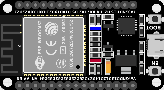
Pin Configuration and Descriptions

The ESP32 has a flexible pinout, with GPIO pins that can be configured for multiple functions. Below is a summary of the key pins:

Pin Name Function Description
GPIO0 Input/Output, Boot Mode Select Used for boot mode selection during startup.
GPIO1 (TXD0) UART TX Default UART0 transmit pin.
GPIO3 (RXD0) UART RX Default UART0 receive pin.
GPIO12-15 Input/Output, SPI SPI interface pins (MISO, MOSI, SCK, CS).
GPIO34-39 Input Only ADC input pins, cannot be used as outputs.
EN Enable Active-high enable pin to reset the chip.
3V3 Power Supply 3.3V power input.
GND Ground Ground connection.

Note: The exact pinout may vary depending on the ESP32 module (e.g., ESP32-WROOM-32, ESP32-WROVER).

Usage Instructions

How to Use the ESP32 in a Circuit

  1. Power Supply: Provide a stable 3.3V power supply to the 3V3 pin. Ensure the current rating of the power source meets the ESP32's requirements.
  2. Boot Mode: Connect GPIO0 to GND during startup to enter bootloader mode for programming.
  3. Programming: Use a USB-to-serial adapter or a development board (e.g., ESP32 DevKit) to upload code via UART.
  4. Peripherals: Connect sensors, actuators, or other devices to the GPIO pins. Configure the pins in your code for the desired functionality (e.g., input, output, ADC, PWM).

Important Considerations and Best Practices

  • Voltage Levels: The ESP32 operates at 3.3V logic levels. Avoid connecting 5V signals directly to its GPIO pins.
  • Power Consumption: Use deep sleep mode to minimize power consumption in battery-powered applications.
  • Antenna Placement: Ensure the onboard antenna has sufficient clearance from metal objects to avoid signal interference.
  • Pull-up/Pull-down Resistors: Some GPIO pins require external pull-up or pull-down resistors for proper operation.

Example: Connecting the ESP32 to an Arduino UNO

The ESP32 can be programmed using the Arduino IDE. Below is an example of how to blink an LED connected to GPIO2:

// Blink an LED connected to GPIO2 on the ESP32

// Define the GPIO pin for the LED
const int ledPin = 2;

void setup() {
  // Set the LED pin as an output
  pinMode(ledPin, OUTPUT);
}

void loop() {
  // Turn the LED on
  digitalWrite(ledPin, HIGH);
  delay(1000); // Wait for 1 second

  // Turn the LED off
  digitalWrite(ledPin, LOW);
  delay(1000); // Wait for 1 second
}

Tip: Install the ESP32 board package in the Arduino IDE before uploading code. Go to File > Preferences, add the ESP32 board URL to the Additional Board Manager URLs, and install the package via the Board Manager.

Troubleshooting and FAQs

Common Issues and Solutions

  1. ESP32 Not Detected by Computer

    • Ensure the correct USB driver is installed for your USB-to-serial adapter.
    • Check the USB cable for damage or try a different cable.
  2. Upload Fails with "Failed to Connect" Error

    • Hold the BOOT button (or connect GPIO0 to GND) while pressing the EN button to enter bootloader mode.
    • Verify the correct COM port and board type are selected in the Arduino IDE.
  3. Wi-Fi Connection Issues

    • Ensure the Wi-Fi credentials (SSID and password) are correct.
    • Check for interference or weak signal strength.
  4. GPIO Pin Not Working

    • Verify the pin is not being used by another peripheral (e.g., ADC, SPI).
    • Check for proper pull-up or pull-down resistor configuration.

FAQs

Q: Can the ESP32 operate on 5V?
A: No, the ESP32 operates at 3.3V. Applying 5V to its GPIO pins can damage the chip.

Q: How do I reset the ESP32?
A: Press the EN button on the development board or toggle the EN pin.

Q: Can I use the ESP32 for Bluetooth audio?
A: Yes, the ESP32 supports Bluetooth audio via the A2DP profile, but additional libraries may be required.

Q: What is the maximum range of the ESP32's Wi-Fi?
A: The range depends on environmental factors but typically extends up to 100 meters in open space.

For more information, refer to the official ESP32 datasheet and technical reference manual.