How to Use Charger Micro USB 5V 3A: Examples, Pinouts, and Specs
Introduction
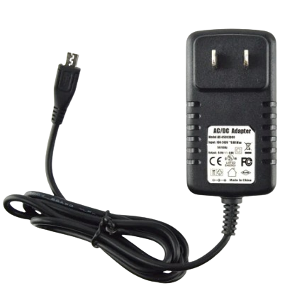
The Charger Micro USB 5V 3A (Manufacturer: AC, Part ID: Charger) is a compact and efficient power supply device designed to deliver a stable 5V output with a maximum current of 3A. It connects via a standard Micro USB interface, making it compatible with a wide range of electronic devices, including smartphones, tablets, single-board computers (e.g., Raspberry Pi), and other USB-powered gadgets.
Explore Projects Built with Charger Micro USB 5V 3A


Explore Projects Built with Charger Micro USB 5V 3A
Common Applications and Use Cases
- Charging smartphones, tablets, and other portable devices.
- Powering single-board computers like Raspberry Pi or Arduino-based projects.
- Supplying power to IoT devices and small electronic circuits.
- General-purpose USB power supply for prototyping and testing.
Technical Specifications
The following table outlines the key technical details of the Charger Micro USB 5V 3A:
| Parameter | Specification |
|---|---|
| Manufacturer | AC |
| Part ID | Charger |
| Input Voltage | 100-240V AC, 50/60Hz |
| Output Voltage | 5V DC |
| Maximum Output Current | 3A |
| Connector Type | Micro USB |
| Cable Length | Typically 1 meter (varies by model) |
| Efficiency | ≥ 85% |
| Operating Temperature | 0°C to 40°C |
| Storage Temperature | -20°C to 70°C |
| Safety Features | Overcurrent, overvoltage, and short-circuit protection |
Pin Configuration and Descriptions
The Micro USB connector used in this charger has the following pinout:
| Pin Number | Name | Description |
|---|---|---|
| 1 | VBUS (+5V) | Supplies 5V DC power to the connected device. |
| 2 | D- (Data -) | Data line for USB communication (not used for power). |
| 3 | D+ (Data +) | Data line for USB communication (not used for power). |
| 4 | ID | Identification pin (used in OTG devices, typically unused). |
| 5 | GND (Ground) | Ground connection for the power supply. |
Usage Instructions
How to Use the Component in a Circuit
- Connect the Charger to a Power Source: Plug the charger into a standard AC outlet (100-240V AC).
- Connect the Micro USB Output: Attach the Micro USB connector to the device or circuit requiring power.
- Verify Compatibility: Ensure the connected device operates at 5V and does not exceed a current draw of 3A.
- Monitor Operation: Check for proper operation of the powered device. If the device does not power on, verify the connections and ensure the charger is functioning.
Important Considerations and Best Practices
- Avoid Overloading: Do not connect devices that require more than 3A, as this may damage the charger or the connected device.
- Use Quality Cables: Ensure the Micro USB cable used is of good quality and capable of handling 3A current to prevent voltage drops.
- Ventilation: Operate the charger in a well-ventilated area to prevent overheating.
- Check for Damage: Inspect the charger and cable for physical damage before use. Do not use if the insulation is broken or the connector is loose.
- Arduino Compatibility: This charger can be used to power Arduino boards (e.g., Arduino UNO) via the USB port. Ensure the Arduino's power requirements match the charger's output.
Example: Powering an Arduino UNO
To power an Arduino UNO using the Charger Micro USB 5V 3A:
- Connect the Micro USB cable to the charger.
- Plug the other end of the cable into the Arduino UNO's USB port.
- The Arduino will power on, and the onboard LED will light up.
If you are using the Arduino UNO in a project, you can upload the following simple code to test the setup:
// Blink an LED on pin 13 to verify the Arduino is powered correctly
void setup() {
  pinMode(13, OUTPUT); // Set pin 13 as an output pin
}

void loop() {
  digitalWrite(13, HIGH); // Turn the LED on
  delay(1000);            // Wait for 1 second
  digitalWrite(13, LOW);  // Turn the LED off
  delay(1000);            // Wait for 1 second
}
Note:
- The charger does not provide data communication functionality. It is strictly a power supply device.
Troubleshooting and FAQs
Common Issues Users Might Face
Device Not Powering On:
- Cause: The device may require more than 3A or may not be compatible with a 5V power supply.
- Solution: Verify the device's power requirements and ensure they match the charger's specifications.
Charger Overheating:
- Cause: Prolonged use at maximum load or poor ventilation.
- Solution: Reduce the load or ensure the charger is used in a well-ventilated area.
Loose Connection:
- Cause: Worn-out or damaged Micro USB cable.
- Solution: Replace the cable with a high-quality, compatible Micro USB cable.
Intermittent Power Supply:
- Cause: Faulty charger or cable.
- Solution: Test with a different charger or cable to isolate the issue.
FAQs
Q1: Can this charger be used with a Raspberry Pi?
A1: Yes, the charger is suitable for powering Raspberry Pi models that require 5V and up to 3A. Ensure the total current draw of connected peripherals does not exceed 3A.
Q2: Is this charger compatible with fast-charging protocols?
A2: No, this charger provides a fixed 5V output and does not support fast-charging protocols like Quick Charge or Power Delivery.
Q3: Can I use this charger to power multiple devices simultaneously?
A3: It is not recommended to split the output to power multiple devices, as this may exceed the 3A limit and cause instability.
Q4: What safety features does this charger have?
A4: The charger includes overcurrent, overvoltage, and short-circuit protection to ensure safe operation.
By following the guidelines and best practices outlined in this documentation, users can safely and effectively utilize the Charger Micro USB 5V 3A for their electronic projects and devices.