How to Use MyoWare Muscle Sensor: Examples, Pinouts, and Specs
Introduction
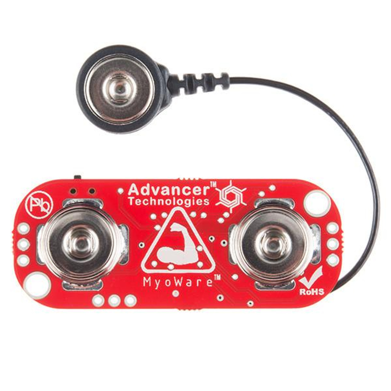
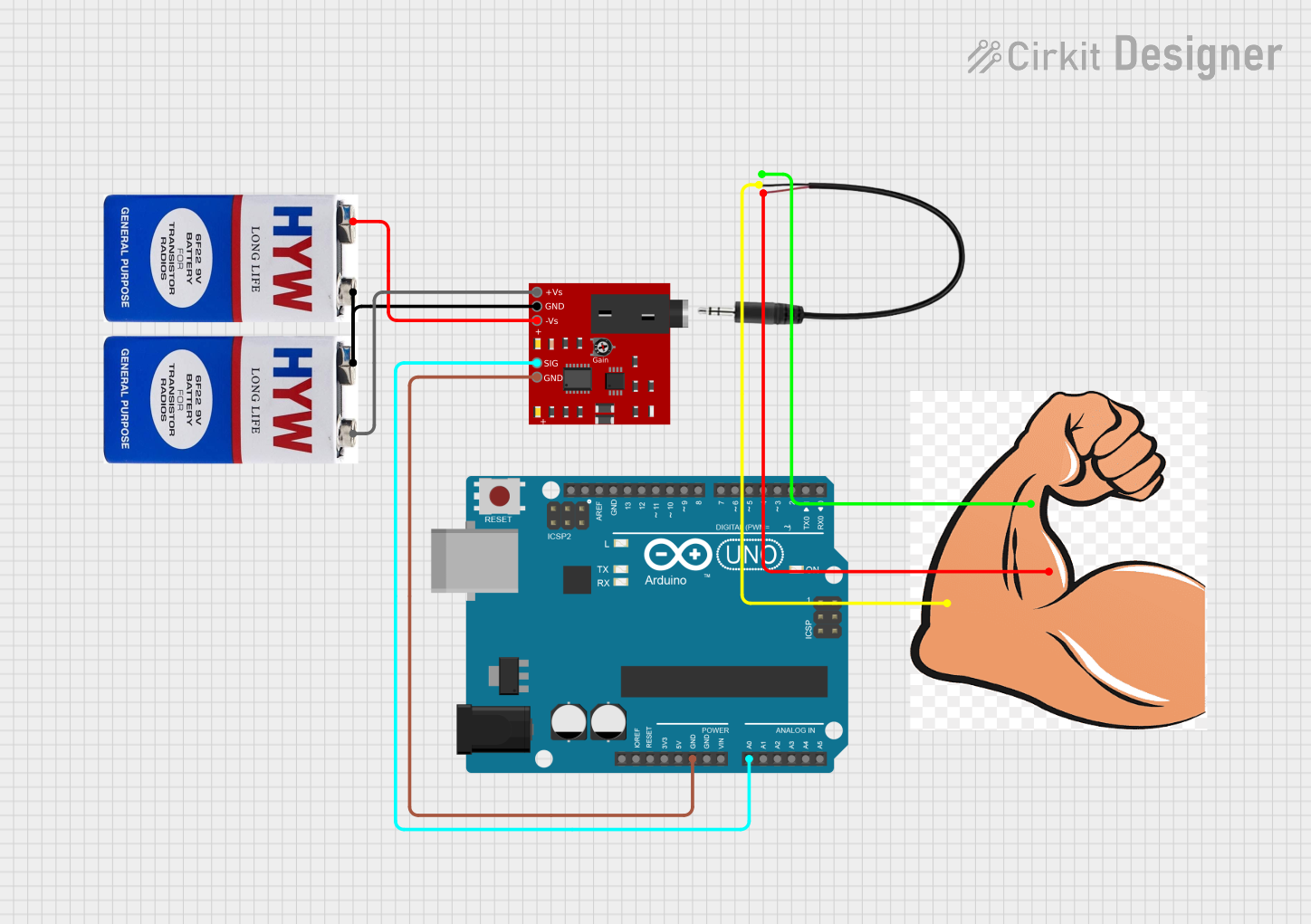
The MyoWare Muscle Sensor, manufactured by Sensor with part ID Muscles, is a sophisticated device designed to measure the electrical activity of muscles. This sensor is commonly used in biomedical applications to monitor muscle activity and control prosthetic devices. It provides a simple and effective way to interface with the human body, making it an essential tool for researchers, hobbyists, and developers working on biofeedback, rehabilitation, and human-computer interaction projects.
Explore Projects Built with MyoWare Muscle Sensor
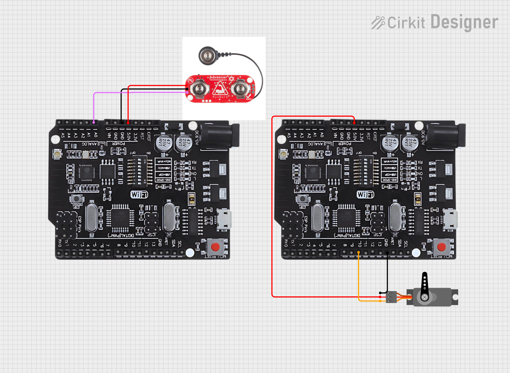
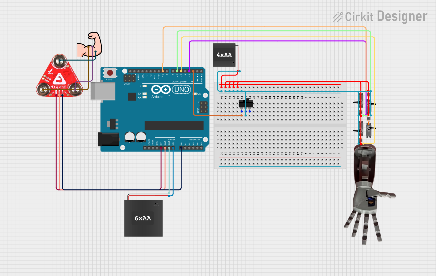
Explore Projects Built with MyoWare Muscle Sensor
Technical Specifications
The MyoWare Muscle Sensor is designed to be user-friendly and versatile. Below are the key technical details and pin configurations:
Key Technical Details
| Parameter | Value |
|---|---|
| Operating Voltage | 3.1V - 5.5V |
| Operating Current | ~9mA |
| Output Voltage | 0V - Vs (Supply Voltage) |
| Gain | Adjustable via potentiometer |
| Electrode Connector | Snap-style |
| Dimensions | 1.0" x 1.0" (25.4mm x 25.4mm) |
Pin Configuration and Descriptions
| Pin Name | Pin Number | Description |
|---|---|---|
| Vs | 1 | Supply Voltage (3.1V - 5.5V) |
| GND | 2 | Ground |
| SIG | 3 | Signal Output (0V - Vs) |
| REF | 4 | Reference Voltage (optional, typically GND) |
Usage Instructions
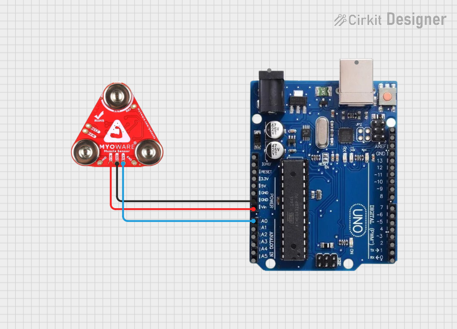
How to Use the Component in a Circuit
Powering the Sensor:
- Connect the Vs pin to a 3.1V - 5.5V power supply.
- Connect the GND pin to the ground of your power supply.
Connecting Electrodes:
- Attach the snap-style electrodes to the muscle you wish to monitor.
- Ensure the electrodes are placed correctly: one on the muscle belly, one on the muscle end, and one on a neutral site (reference).
Reading the Signal:
- Connect the SIG pin to an analog input of your microcontroller (e.g., Arduino UNO).
- Optionally, connect the REF pin to the ground if you need a reference voltage.
Important Considerations and Best Practices
- Electrode Placement: Proper placement of electrodes is crucial for accurate readings. Ensure the skin is clean and dry before attaching electrodes.
- Signal Conditioning: The output signal may need filtering or amplification depending on your application.
- Power Supply: Use a stable power supply to avoid noise in the signal.
- Calibration: Adjust the gain using the onboard potentiometer to suit your specific needs.
Example Code for Arduino UNO
Below is an example code to read the MyoWare Muscle Sensor output using an Arduino UNO:
// Define the analog pin connected to the MyoWare Muscle Sensor
const int muscleSensorPin = A0;

// Variable to store the sensor value
int sensorValue = 0;

void setup() {
  // Initialize serial communication at 9600 baud rate
  Serial.begin(9600);
}

void loop() {
  // Read the analog value from the muscle sensor
  sensorValue = analogRead(muscleSensorPin);

  // Print the sensor value to the Serial Monitor
  Serial.println(sensorValue);

  // Small delay to stabilize the readings
  delay(10);
}
Troubleshooting and FAQs
Common Issues Users Might Face
No Signal Output:
- Solution: Check the power connections and ensure the sensor is properly powered. Verify the electrode placement and ensure good contact with the skin.
Noisy Signal:
- Solution: Ensure the power supply is stable. Use shielded cables and keep the sensor away from electromagnetic interference sources. Consider adding a low-pass filter to the signal.
Weak Signal:
- Solution: Adjust the gain using the onboard potentiometer. Ensure the electrodes are placed correctly and the skin is clean.
FAQs
Q1: Can I use the MyoWare Muscle Sensor with a battery?
- A1: Yes, the sensor can be powered by a battery within the operating voltage range (3.1V - 5.5V).
Q2: How do I clean the electrodes?
- A2: Use a damp cloth to clean the electrodes. Avoid using harsh chemicals or submerging them in water.
Q3: Can I use the sensor for long-term monitoring?
- A3: Yes, but ensure the electrodes are securely attached and check them periodically for good contact.
Q4: What type of electrodes should I use?
- A4: Use snap-style electrodes designed for EMG applications. Ensure they are compatible with the MyoWare Muscle Sensor.
By following this documentation, users can effectively utilize the MyoWare Muscle Sensor in their projects, ensuring accurate and reliable muscle activity monitoring.