How to Use lora esp32 module: Examples, Pinouts, and Specs
Introduction
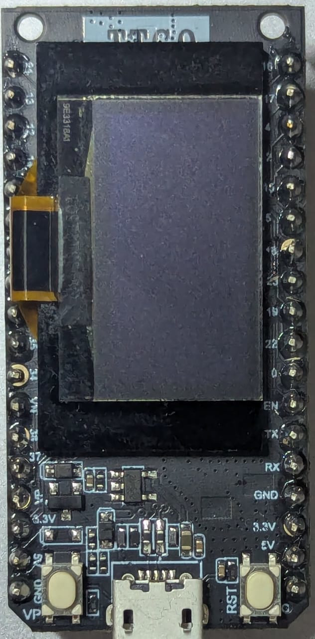
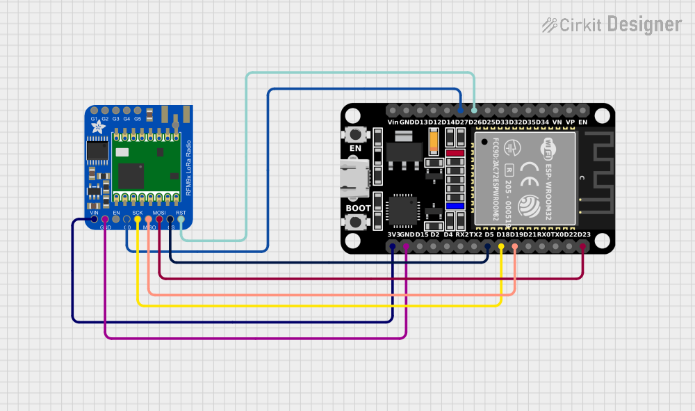
The LoRa ESP32 Sensor Module by LilyGO is a compact microcontroller module that combines the powerful ESP32 chip with LoRa (Long Range) communication technology. This module is designed for low-power, long-distance wireless communication, making it ideal for Internet of Things (IoT) applications. It supports dual-core processing, Wi-Fi, Bluetooth, and LoRa, providing a versatile platform for a wide range of projects.
Explore Projects Built with lora esp32 module
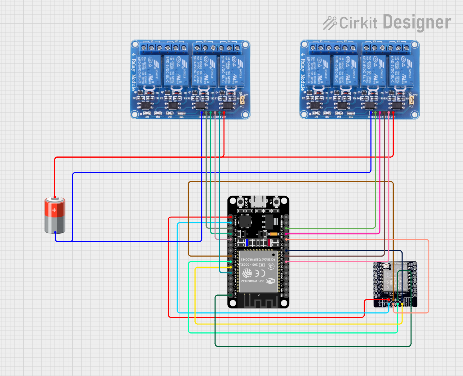
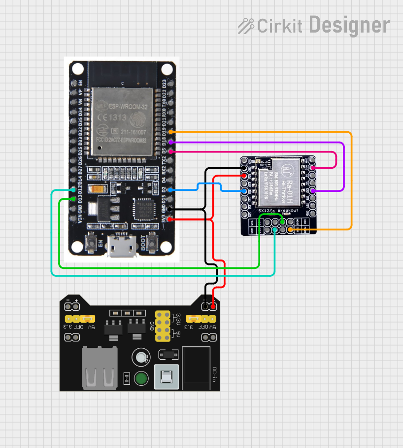
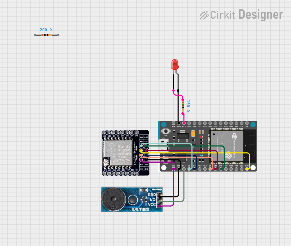
Explore Projects Built with lora esp32 module
Common Applications and Use Cases
- Smart agriculture and environmental monitoring
- Remote sensor networks
- Home automation and smart cities
- Industrial IoT (IIoT) systems
- Asset tracking and geolocation
- Low-power, long-range wireless communication projects
Technical Specifications
Below are the key technical details of the LoRa ESP32 Sensor Module:
| Specification | Details |
|---|---|
| Manufacturer | LilyGO |
| Part ID | LoRa ESP32 Sensor Module |
| Microcontroller | ESP32 (dual-core, 32-bit processor) |
| Wireless Communication | LoRa, Wi-Fi (802.11 b/g/n), Bluetooth 4.2 |
| LoRa Frequency Bands | 433 MHz / 868 MHz / 915 MHz (region-specific) |
| Flash Memory | 4 MB |
| SRAM | 520 KB |
| Operating Voltage | 3.3V |
| Input Voltage Range | 5V (via USB) or 3.3V (via pin headers) |
| Power Consumption | Ultra-low power consumption in deep sleep mode |
| GPIO Pins | 22 GPIO pins (configurable for digital I/O, PWM, ADC, DAC, etc.) |
| Interfaces | SPI, I2C, UART, ADC, DAC, PWM |
| Antenna | External LoRa antenna (via IPEX connector) |
| Dimensions | 51 mm x 25 mm |
Pin Configuration and Descriptions
The following table outlines the key pin configurations for the module:
| Pin | Name | Description |
|---|---|---|
| 1 | 3V3 | 3.3V power supply input/output |
| 2 | GND | Ground |
| 3 | GPIO0 | General-purpose I/O pin (used for boot mode selection) |
| 4 | GPIO16 | General-purpose I/O pin (LoRa chip NSS/CS by default) |
| 5 | GPIO17 | General-purpose I/O pin (LoRa chip RST by default) |
| 6 | GPIO18 | SPI Clock (SCK) |
| 7 | GPIO19 | SPI Master-In-Slave-Out (MISO) |
| 8 | GPIO23 | SPI Master-Out-Slave-In (MOSI) |
| 9 | GPIO26 | LoRa DIO0 (interrupt pin for LoRa communication) |
| 10 | EN | Enable pin (used to reset the ESP32 module) |
| 11 | VIN | Power input (5V via USB or external power source) |
| 12 | TXD0 | UART0 Transmit |
| 13 | RXD0 | UART0 Receive |
Usage Instructions
How to Use the Component in a Circuit
Powering the Module:
- Connect the VIN pin to a 5V power source or use the USB interface for power.
- Ensure the GND pin is connected to the ground of your circuit.
Connecting the LoRa Antenna:
- Attach the external LoRa antenna to the IPEX connector for optimal signal strength.
Programming the Module:
- Use the USB interface to connect the module to your computer.
- Install the necessary drivers for the ESP32 chip (e.g., CP210x or CH340 drivers).
- Use the Arduino IDE or PlatformIO to write and upload code to the module.
Interfacing with Sensors and Peripherals:
- Use the GPIO pins to connect sensors, actuators, or other peripherals.
- Configure the pins in your code for digital I/O, PWM, ADC, or other functions as needed.
LoRa Communication:
- Use the SPI pins (GPIO16, GPIO18, GPIO19, GPIO23) to interface with the LoRa transceiver.
- Configure the LoRa settings (frequency, spreading factor, bandwidth, etc.) in your code.
Important Considerations and Best Practices
- Power Supply: Ensure a stable 3.3V or 5V power supply to avoid damage to the module.
- Antenna Placement: Position the LoRa antenna away from other components to minimize interference.
- Deep Sleep Mode: Use the deep sleep mode to reduce power consumption in battery-powered applications.
- Region-Specific Frequency: Verify and configure the LoRa frequency band according to your region's regulations.
Example Code for Arduino UNO
Below is an example of how to use the LoRa ESP32 module with the Arduino IDE for basic LoRa communication:
#include <SPI.h>
#include <LoRa.h> // Include the LoRa library

#define SS 16    // LoRa chip select pin
#define RST 17   // LoRa reset pin
#define DIO0 26  // LoRa interrupt pin

void setup() {
  Serial.begin(9600); // Initialize serial communication
  while (!Serial);

  Serial.println("Initializing LoRa module...");

  // Initialize LoRa module
  LoRa.setPins(SS, RST, DIO0); // Set LoRa module pins
  if (!LoRa.begin(915E6)) {    // Set frequency to 915 MHz (adjust for your region)
    Serial.println("LoRa initialization failed!");
    while (1);
  }

  Serial.println("LoRa initialized successfully!");
}

void loop() {
  Serial.println("Sending packet...");
  LoRa.beginPacket();          // Start a new LoRa packet
  LoRa.print("Hello, LoRa!");  // Add data to the packet
  LoRa.endPacket();            // Send the packet

  delay(5000); // Wait 5 seconds before sending the next packet
}
Troubleshooting and FAQs
Common Issues and Solutions
LoRa Initialization Fails:
- Cause: Incorrect wiring or frequency mismatch.
- Solution: Double-check the wiring and ensure the frequency matches your region's regulations.
No LoRa Communication:
- Cause: Antenna not connected or poor signal strength.
- Solution: Ensure the antenna is securely connected and positioned correctly.
Module Not Detected by Computer:
- Cause: Missing drivers or faulty USB cable.
- Solution: Install the correct drivers (e.g., CP210x or CH340) and try a different USB cable.
High Power Consumption:
- Cause: Module not in deep sleep mode.
- Solution: Implement deep sleep mode in your code to reduce power usage.
FAQs
Q: Can I use this module with a 5V logic level microcontroller?
A: No, the module operates at 3.3V logic levels. Use a level shifter if needed.Q: What is the maximum range of LoRa communication?
A: The range depends on environmental factors but can reach up to 10 km in open areas.Q: Can I use this module for Wi-Fi and LoRa simultaneously?
A: Yes, but it may require careful resource management due to shared hardware.Q: How do I update the firmware?
A: Use the USB interface and a compatible programming tool like the Arduino IDE or ESP-IDF.