How to Use step up dc to dc: Examples, Pinouts, and Specs
Introduction
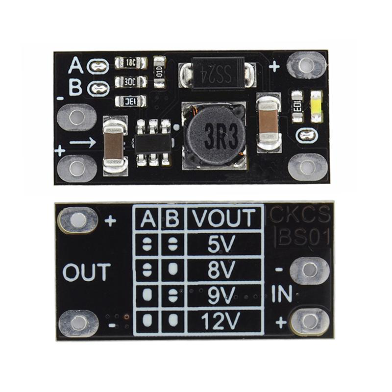
A step-up DC to DC converter, also known as a boost converter, is an electronic component designed to increase the input voltage to a higher output voltage while maintaining the same power level (minus efficiency losses). Manufactured by Arduino, this component is ideal for applications where a higher voltage is required from a lower voltage power source, such as batteries or solar panels.
Explore Projects Built with step up dc to dc


Explore Projects Built with step up dc to dc
Common Applications and Use Cases
- Powering devices that require higher voltage from a low-voltage battery (e.g., 3.7V to 12V).
- Boosting voltage for LED strips, motor drivers, or sensors.
- Renewable energy systems, such as solar-powered devices.
- Portable electronics and USB-powered devices.
Technical Specifications
Below are the key technical details for the Arduino Step-Up DC to DC Converter:
| Parameter | Value |
|---|---|
| Input Voltage Range | 2V to 24V |
| Output Voltage Range | 5V to 28V (adjustable) |
| Maximum Output Current | 2A (depends on input voltage) |
| Efficiency | Up to 95% (depending on load) |
| Switching Frequency | 150 kHz |
| Operating Temperature | -40°C to +85°C |
| Dimensions | 22mm x 17mm x 4mm |
Pin Configuration and Descriptions
The Arduino Step-Up DC to DC Converter typically has four pins or terminals:
| Pin/Terminal | Label | Description |
|---|---|---|
| 1 | VIN | Input voltage terminal. Connect to the positive terminal of the power source. |
| 2 | GND | Ground terminal. Connect to the negative terminal of the power source. |
| 3 | VOUT | Output voltage terminal. Provides the boosted voltage to the load. |
| 4 | ADJ | Adjustment pin. Used to set the desired output voltage (via a potentiometer). |
Usage Instructions
How to Use the Component in a Circuit
Connect the Input Voltage:
- Attach the positive terminal of your power source to the
VINpin. - Connect the negative terminal of your power source to the
GNDpin.
- Attach the positive terminal of your power source to the
Set the Desired Output Voltage:
- Use a small screwdriver to adjust the onboard potentiometer connected to the
ADJpin. - Measure the output voltage at the
VOUTpin using a multimeter while adjusting the potentiometer.
- Use a small screwdriver to adjust the onboard potentiometer connected to the
Connect the Load:
- Attach the positive terminal of your load to the
VOUTpin. - Connect the negative terminal of your load to the
GNDpin.
- Attach the positive terminal of your load to the
Power On:
- Turn on the power source. The converter will boost the input voltage to the desired output voltage.
Important Considerations and Best Practices
- Input Voltage Range: Ensure the input voltage is within the specified range (2V to 24V). Exceeding this range may damage the component.
- Output Current Limit: Do not exceed the maximum output current of 2A. Use a heat sink if operating near the maximum current for extended periods.
- Efficiency: For optimal efficiency, keep the input voltage as close as possible to the desired output voltage.
- Load Connection: Always connect the load after setting the desired output voltage to avoid overvoltage damage.
- Arduino Integration: This component can be used with Arduino boards to power sensors or modules requiring higher voltage.
Example: Using with Arduino UNO
Below is an example of using the step-up DC to DC converter to power a 12V motor from a 5V Arduino UNO power source.
Circuit Connections
- Connect the Arduino UNO's 5V pin to the
VINpin of the converter. - Connect the Arduino UNO's GND pin to the
GNDpin of the converter. - Adjust the converter's output voltage to 12V using the potentiometer.
- Connect the motor's positive terminal to the
VOUTpin and the negative terminal to theGNDpin.
Arduino Code Example
// Example code to control a 12V motor powered by a step-up DC to DC converter
// connected to an Arduino UNO. The motor is controlled using a PWM signal.

const int motorPin = 9; // PWM pin connected to motor driver input

void setup() {
  pinMode(motorPin, OUTPUT); // Set motor pin as output
}

void loop() {
  // Gradually increase motor speed
  for (int speed = 0; speed <= 255; speed++) {
    analogWrite(motorPin, speed); // Write PWM signal to motor
    delay(20); // Wait 20ms before increasing speed
  }

  // Gradually decrease motor speed
  for (int speed = 255; speed >= 0; speed--) {
    analogWrite(motorPin, speed); // Write PWM signal to motor
    delay(20); // Wait 20ms before decreasing speed
  }
}
Troubleshooting and FAQs
Common Issues and Solutions
No Output Voltage:
- Cause: Input voltage is too low or not connected properly.
- Solution: Verify the input voltage is within the specified range and check all connections.
Output Voltage is Incorrect:
- Cause: Potentiometer is not adjusted correctly.
- Solution: Use a multimeter to measure the output voltage and adjust the potentiometer.
Overheating:
- Cause: Excessive current draw or poor ventilation.
- Solution: Ensure the load does not exceed the maximum current rating. Use a heat sink or improve airflow.
Low Efficiency:
- Cause: Large difference between input and output voltage.
- Solution: Minimize the voltage difference between input and output for better efficiency.
FAQs
Q: Can I use this converter to power a 12V LED strip from a 3.7V battery?
A: Yes, as long as the current draw of the LED strip does not exceed 2A.Q: How do I know if the converter is damaged?
A: If there is no output voltage despite correct connections and input voltage, the converter may be damaged.Q: Can I use this with a solar panel?
A: Yes, but ensure the solar panel's output voltage and current are within the converter's input range.Q: Is the output voltage stable?
A: Yes, the converter provides a stable output voltage under normal operating conditions.