How to Use SparkFun Blynk Board - ESP8266: Examples, Pinouts, and Specs
Introduction
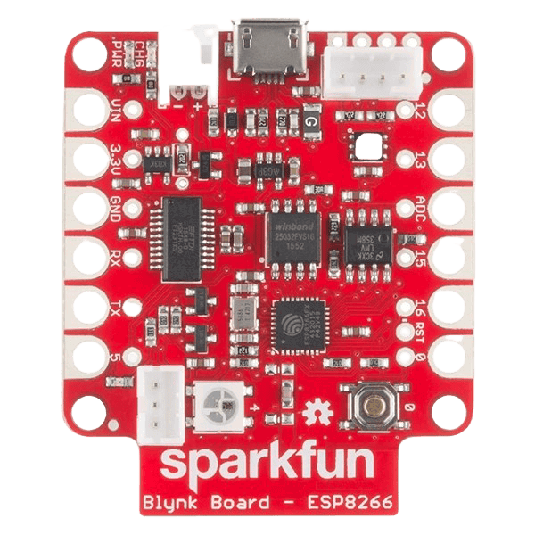
The SparkFun Blynk Board - ESP8266 (WRL-13794) is a versatile development board designed for Internet of Things (IoT) applications. It features the popular ESP8266 Wi-Fi module, enabling seamless wireless connectivity. The board is pre-configured to work with the Blynk app, allowing users to remotely control and monitor devices via a smartphone or tablet. This makes it an excellent choice for beginners and professionals looking to prototype IoT solutions quickly.
Explore Projects Built with SparkFun Blynk Board - ESP8266

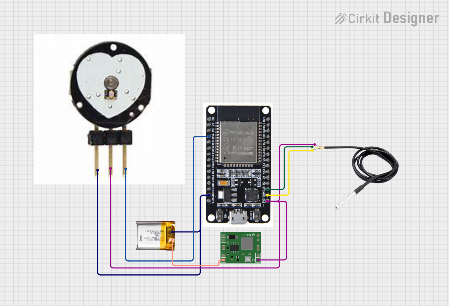
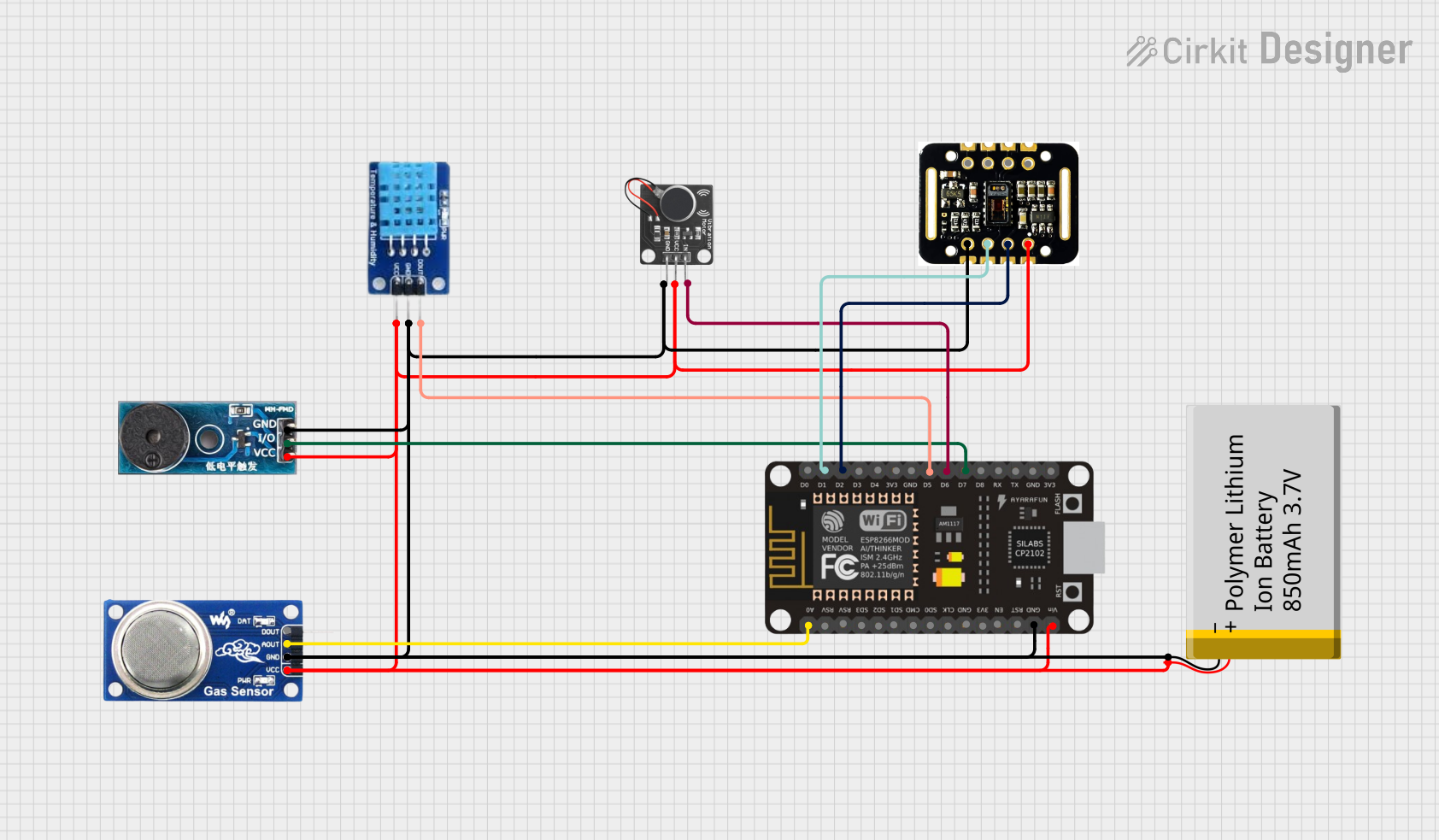
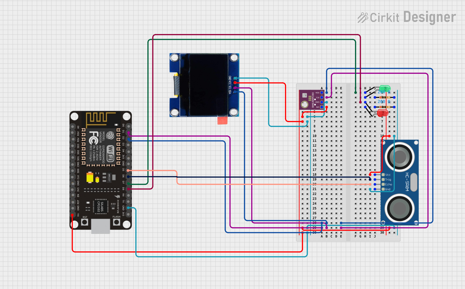
Explore Projects Built with SparkFun Blynk Board - ESP8266
Common Applications
- Home automation systems
- Remote monitoring and control of sensors
- IoT-enabled appliances
- Educational projects for learning IoT and wireless communication
- Prototyping smart devices
Technical Specifications
Below are the key technical details of the SparkFun Blynk Board - ESP8266:
| Specification | Details |
|---|---|
| Microcontroller | ESP8266 (80 MHz, 32-bit processor) |
| Wi-Fi | 802.11 b/g/n |
| Operating Voltage | 3.3V |
| Input Voltage (USB) | 5V (via micro-USB connector) |
| Flash Memory | 4 MB |
| GPIO Pins | 11 (including PWM, I2C, and UART support) |
| Analog Input | 1 (10-bit ADC, 0–1V range) |
| Power Consumption | ~70 mA (active), ~10 µA (deep sleep mode) |
| Dimensions | 1.8" x 1.0" (45.7 mm x 25.4 mm) |
| Compatibility | Works with Blynk app (iOS and Android) |
Pin Configuration and Descriptions
The SparkFun Blynk Board has a simple pinout, as shown below:
| Pin | Label | Description |
|---|---|---|
| 1 | GND | Ground connection |
| 2 | 3.3V | 3.3V power output |
| 3 | TX | UART Transmit (for serial communication) |
| 4 | RX | UART Receive (for serial communication) |
| 5 | D0-D8 | General-purpose digital I/O pins (PWM capable on select pins) |
| 6 | A0 | Analog input (0–1V range) |
| 7 | RST | Reset pin (active low) |
| 8 | EN | Enable pin (pull high to enable the board) |
Usage Instructions
How to Use the SparkFun Blynk Board in a Circuit
Powering the Board:
- Connect the board to a computer or USB power source using a micro-USB cable.
- Ensure the input voltage is 5V via USB; the onboard regulator will step it down to 3.3V.
Connecting to the Blynk App:
- Download the Blynk app from the iOS App Store or Google Play Store.
- Create a new project in the app and select "ESP8266" as the device.
- Copy the authentication token provided by the app.
Programming the Board:
- Install the Arduino IDE and add the ESP8266 board package via the Boards Manager.
- Install the Blynk library by navigating to Sketch > Include Library > Manage Libraries, then search for "Blynk".
- Use the example code below to connect the board to your Wi-Fi network and the Blynk app.
Example Code for Arduino IDE
#define BLYNK_PRINT Serial  // Enables serial monitor debugging
#include <ESP8266WiFi.h>
#include <BlynkSimpleEsp8266.h>

// Replace with your Wi-Fi credentials
char ssid[] = "YourWiFiNetwork";       // Your Wi-Fi SSID
char pass[] = "YourWiFiPassword";     // Your Wi-Fi password

// Replace with your Blynk authentication token
char auth[] = "YourBlynkAuthToken";

void setup() {
  Serial.begin(9600);  // Initialize serial communication
  Blynk.begin(auth, ssid, pass);  // Connect to Blynk server
}

void loop() {
  Blynk.run();  // Run Blynk process
}
Important Considerations
- Voltage Levels: The ESP8266 operates at 3.3V. Avoid applying 5V directly to the GPIO pins.
- Wi-Fi Signal Strength: Ensure the board is within range of your Wi-Fi router for stable connectivity.
- Power Supply: Use a reliable 5V USB power source to avoid unexpected resets or instability.
Troubleshooting and FAQs
Common Issues and Solutions
The board does not connect to Wi-Fi:
- Double-check the SSID and password in your code.
- Ensure the Wi-Fi network is 2.4 GHz, as the ESP8266 does not support 5 GHz networks.
The board is not recognized by the computer:
- Install the necessary USB-to-serial drivers (e.g., CP2102 or CH340, depending on your board).
- Try a different USB cable, as some cables are power-only and do not support data transfer.
Blynk app shows the device as offline:
- Verify that the authentication token in your code matches the one in the app.
- Check the serial monitor for error messages during the connection process.
GPIO pins are not functioning as expected:
- Ensure the pins are configured correctly in your code (e.g., as INPUT or OUTPUT).
- Avoid exceeding the maximum current rating of the pins (12 mA per pin).
FAQs
Q: Can I use the SparkFun Blynk Board without the Blynk app?
A: Yes, the board can be programmed using the Arduino IDE for standalone applications without the Blynk app.
Q: What is the maximum range of the Wi-Fi module?
A: The ESP8266 has a typical range of 30–50 meters indoors and up to 100 meters in open spaces, depending on environmental factors.
Q: Can I power the board using a battery?
A: Yes, you can use a 3.7V LiPo battery connected to the 3.3V pin, but ensure proper voltage regulation.
This concludes the documentation for the SparkFun Blynk Board - ESP8266. For further assistance, refer to the official SparkFun resources or community forums.