How to Use IO Expander MCP23017 Breakout: Examples, Pinouts, and Specs
Introduction
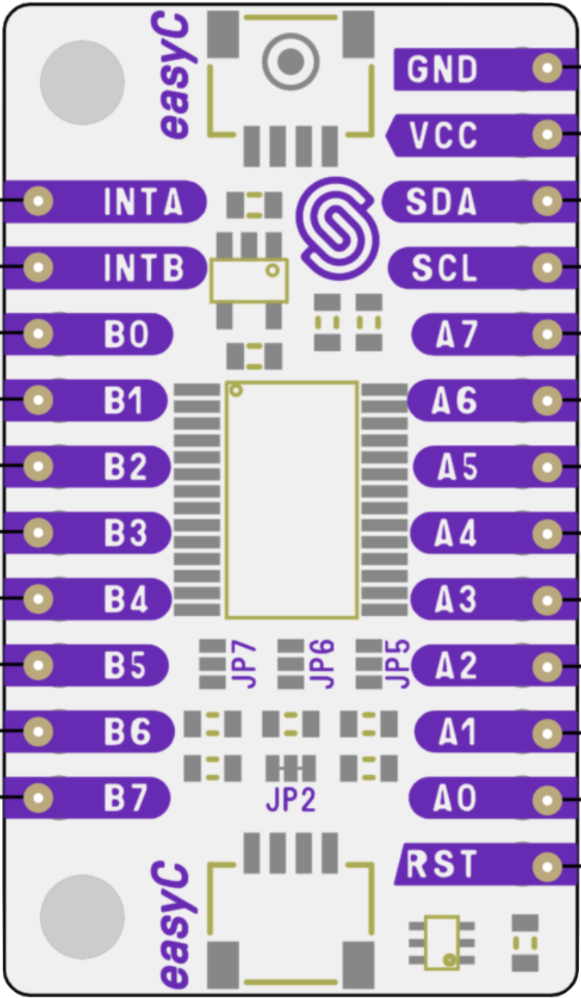
The MCP23017 IO Expander Breakout, manufactured by Soldered (Part ID: 333007), is a versatile 16-bit I/O expander that communicates via the I2C protocol. It allows microcontrollers to extend their GPIO capabilities by adding 16 additional input/output pins. This breakout board simplifies the integration of the MCP23017 chip into your projects by providing easy-to-use pin headers and a compact design.
Explore Projects Built with IO Expander MCP23017 Breakout


Explore Projects Built with IO Expander MCP23017 Breakout
Common Applications and Use Cases
- Expanding GPIO pins for microcontrollers like Arduino, Raspberry Pi, or ESP32.
- Controlling multiple LEDs, relays, or other digital devices.
- Reading multiple button inputs or sensors.
- Building keypad matrices or LED grids.
- Projects requiring a large number of digital I/O pins.
Technical Specifications
Key Technical Details
- Chip: MCP23017
- Communication Protocol: I2C (Inter-Integrated Circuit)
- Operating Voltage: 1.8V to 5.5V
- Maximum Current per Pin: 25mA
- Maximum Total Current: 125mA
- I2C Address Range: 0x20 to 0x27 (configurable via address pins)
- Number of GPIO Pins: 16 (organized as two 8-bit ports: PORTA and PORTB)
- Interrupt Capability: Configurable interrupt-on-change for each pin
- Pull-up Resistors: Internal 100kΩ (configurable per pin)
- Operating Temperature: -40°C to +125°C
Pin Configuration and Descriptions
The MCP23017 Breakout board provides access to the following pins:
Power and Communication Pins
| Pin Name | Description |
|---|---|
| VCC | Power supply input (1.8V to 5.5V). |
| GND | Ground connection. |
| SDA | I2C data line. Connect to the SDA pin of the microcontroller. |
| SCL | I2C clock line. Connect to the SCL pin of the microcontroller. |
GPIO Pins
| Pin Name | Description |
|---|---|
| GPA0-GPA7 | General-purpose I/O pins for PORTA. Configurable as input or output. |
| GPB0-GPB7 | General-purpose I/O pins for PORTB. Configurable as input or output. |
Address Pins
| Pin Name | Description |
|---|---|
| A0, A1, A2 | Address selection pins. Used to set the I2C address (0x20 to 0x27). |
Interrupt Pins
| Pin Name | Description |
|---|---|
| INTA | Interrupt output for PORTA. Active-low. |
| INTB | Interrupt output for PORTB. Active-low. |
Usage Instructions
How to Use the MCP23017 Breakout in a Circuit
- Power the Breakout Board: Connect the VCC pin to a 3.3V or 5V power source and the GND pin to ground.
- Connect I2C Lines: Connect the SDA and SCL pins to the corresponding I2C pins on your microcontroller.
- Set the I2C Address: Use the A0, A1, and A2 pins to configure the I2C address. Leave them unconnected (default 0x20) or connect them to VCC/GND to set a custom address.
- Connect GPIO Devices: Attach your input/output devices (e.g., LEDs, buttons, sensors) to the GPA0-GPA7 and GPB0-GPB7 pins.
- Configure GPIO Pins: Use software to configure each pin as an input or output and set their states.
Important Considerations and Best Practices
- Pull-up Resistors: Ensure that the I2C lines (SDA and SCL) have pull-up resistors (typically 4.7kΩ). Some microcontroller boards include these by default.
- Interrupts: If using interrupts, connect the INTA and/or INTB pins to interrupt-capable pins on your microcontroller.
- Power Supply: Ensure the power supply voltage matches the logic level of your microcontroller (e.g., 3.3V or 5V).
- Current Limitations: Do not exceed the maximum current ratings for individual pins (25mA) or the total current (125mA).
Example Code for Arduino UNO
Below is an example of how to use the MCP23017 Breakout with an Arduino UNO to control LEDs and read button inputs.
#include <Wire.h>
#include <Adafruit_MCP23017.h>

// Create an MCP23017 object
Adafruit_MCP23017 mcp;

void setup() {
  Wire.begin(); // Initialize I2C communication
  mcp.begin(0); // Initialize MCP23017 with default address (0x20)

  // Configure GPA0 as output (for an LED)
  mcp.pinMode(0, OUTPUT);

  // Configure GPA1 as input with pull-up resistor (for a button)
  mcp.pinMode(1, INPUT);
  mcp.pullUp(1, HIGH); // Enable internal pull-up resistor
}

void loop() {
  // Read the button state (GPA1)
  bool buttonState = mcp.digitalRead(1);

  // Turn the LED (GPA0) on or off based on the button state
  if (buttonState == LOW) { // Button pressed
    mcp.digitalWrite(0, HIGH); // Turn LED on
  } else {
    mcp.digitalWrite(0, LOW); // Turn LED off
  }

  delay(100); // Small delay for debounce
}
Troubleshooting and FAQs
Common Issues and Solutions
I2C Communication Not Working
- Ensure the SDA and SCL lines are correctly connected to the microcontroller.
- Verify that pull-up resistors are present on the I2C lines.
- Check the I2C address configuration (A0, A1, A2 pins).
GPIO Pins Not Responding
- Confirm that the pins are correctly configured as input or output in the code.
- Check for loose or incorrect connections to the GPIO pins.
Interrupts Not Triggering
- Ensure the INTA/INTB pins are connected to interrupt-capable pins on the microcontroller.
- Verify that interrupt-on-change is enabled for the desired pins in the code.
Overheating or Power Issues
- Ensure the total current drawn by all GPIO pins does not exceed 125mA.
- Verify that the power supply voltage matches the MCP23017's operating range.
FAQs
Q: Can I use multiple MCP23017 Breakouts in the same project?
A: Yes, you can connect up to 8 MCP23017 devices on the same I2C bus by configuring their addresses using the A0, A1, and A2 pins.
Q: What is the maximum I2C speed supported by the MCP23017?
A: The MCP23017 supports I2C speeds up to 1.7MHz (Fast Mode Plus).
Q: Can the MCP23017 handle analog signals?
A: No, the MCP23017 is designed for digital input/output only. Use an ADC (Analog-to-Digital Converter) for analog signals.
Q: Do I need external pull-up resistors for the GPIO pins?
A: No, the MCP23017 has internal pull-up resistors that can be enabled via software. However, external pull-ups may be used if stronger pull-up resistance is required.