Cirkit Designer Logo
Cirkit Designer
Your all-in-one circuit design IDE
Home / 
Component Documentation

How to Use ESP32-POE2: Examples, Pinouts, and Specs

Image of ESP32-POE2
Cirkit Designer LogoDesign with ESP32-POE2 in Cirkit Designer

Introduction

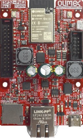
The ESP32-POE2 is a robust microcontroller board designed by Olimex that combines the capabilities of the ESP32-WROVER module with the convenience of Power over Ethernet (PoE). This board is ideal for Internet of Things (IoT) and automation projects that demand both wireless and wired network connections, with the added benefit of powering the device through the Ethernet cable.

Explore Projects Built with ESP32-POE2

Use Cirkit Designer to design, explore, and prototype these projects online. Some projects support real-time simulation. Click "Open Project" to start designing instantly!
ESP32-Powered Smart Home Automation with Relay Control and DHT22 Sensors
Image of Olimex ESP32-POE2 4Ch & 2H and 2 Temp Sensors: A project utilizing ESP32-POE2 in a practical application
This circuit features an ESP32 microcontroller interfaced with two DHT22 temperature and humidity sensors and two relay modules (one 4-channel and one 2-channel). The ESP32 controls the relays and reads data from the sensors, enabling it to manage and monitor environmental conditions and control high-power devices.
Cirkit Designer LogoOpen Project in Cirkit Designer
ESP32-Powered 8-Channel Relay Controller with Wi-Fi Connectivity
Image of Olimex ESP32-POE2 4Ch X 2 Switches: A project utilizing ESP32-POE2 in a practical application
This circuit features an ESP32 microcontroller connected to an 8-channel relay module. The ESP32 controls the relay channels via its GPIO pins, allowing for the switching of external devices or loads through the relays.
Cirkit Designer LogoOpen Project in Cirkit Designer
ESP32-POE-ISO Wi-Fi Controlled 4-Channel Relay Module
Image of ESP32-POE-ISO 4Channel Relay: A project utilizing ESP32-POE2 in a practical application
This circuit features an ESP32-POE-ISO microcontroller connected to a 4-channel 30A 5V relay module. The ESP32 controls the relay channels via its GPIO pins, allowing for the switching of high-power devices through the relay module.
Cirkit Designer LogoOpen Project in Cirkit Designer
ESP32-Powered Smart Relay Control System with DHT22 Sensors
Image of Olimex ESP32-POE2 4Ch 30a + 4CH 10a + 3 DHT Switch: A project utilizing ESP32-POE2 in a practical application
This circuit features an ESP32 microcontroller interfaced with multiple DHT22 temperature and humidity sensors and two relay modules. The ESP32 reads data from the DHT22 sensors and controls the relays, which can be used to switch high-power devices on and off.
Cirkit Designer LogoOpen Project in Cirkit Designer

Explore Projects Built with ESP32-POE2

Use Cirkit Designer to design, explore, and prototype these projects online. Some projects support real-time simulation. Click "Open Project" to start designing instantly!
Image of Olimex ESP32-POE2 4Ch & 2H and 2 Temp Sensors: A project utilizing ESP32-POE2 in a practical application
ESP32-Powered Smart Home Automation with Relay Control and DHT22 Sensors
This circuit features an ESP32 microcontroller interfaced with two DHT22 temperature and humidity sensors and two relay modules (one 4-channel and one 2-channel). The ESP32 controls the relays and reads data from the sensors, enabling it to manage and monitor environmental conditions and control high-power devices.
Cirkit Designer LogoOpen Project in Cirkit Designer
Image of Olimex ESP32-POE2 4Ch X 2 Switches: A project utilizing ESP32-POE2 in a practical application
ESP32-Powered 8-Channel Relay Controller with Wi-Fi Connectivity
This circuit features an ESP32 microcontroller connected to an 8-channel relay module. The ESP32 controls the relay channels via its GPIO pins, allowing for the switching of external devices or loads through the relays.
Cirkit Designer LogoOpen Project in Cirkit Designer
Image of ESP32-POE-ISO 4Channel Relay: A project utilizing ESP32-POE2 in a practical application
ESP32-POE-ISO Wi-Fi Controlled 4-Channel Relay Module
This circuit features an ESP32-POE-ISO microcontroller connected to a 4-channel 30A 5V relay module. The ESP32 controls the relay channels via its GPIO pins, allowing for the switching of high-power devices through the relay module.
Cirkit Designer LogoOpen Project in Cirkit Designer
Image of Olimex ESP32-POE2 4Ch 30a + 4CH 10a + 3 DHT Switch: A project utilizing ESP32-POE2 in a practical application
ESP32-Powered Smart Relay Control System with DHT22 Sensors
This circuit features an ESP32 microcontroller interfaced with multiple DHT22 temperature and humidity sensors and two relay modules. The ESP32 reads data from the DHT22 sensors and controls the relays, which can be used to switch high-power devices on and off.
Cirkit Designer LogoOpen Project in Cirkit Designer

Common Applications and Use Cases

  • Smart home automation
  • Industrial IoT
  • Remote sensors and monitoring
  • Networked devices in locations without easy access to power outlets

Technical Specifications

Key Technical Details

  • Microcontroller: ESP32-WROVER
  • Operating Voltage: 3.3V
  • Input Voltage (PoE): 37V to 57V
  • Input Voltage (USB): 5V
  • Flash Memory: 4MB
  • SRAM: 520KB
  • Wi-Fi: 802.11 b/g/n
  • Bluetooth: v4.2 BR/EDR and BLE
  • Ethernet: 100Mbps

Pin Configuration and Descriptions

Pin Number Function Description
1 GND Ground
2 3V3 3.3V output
3 EN Chip enable. Keep it high (3.3V) to operate.
... ... ...
n IOxx General purpose IO pin

Note: The full pinout for the ESP32-POE2 is extensive and should be referred to in the official Olimex documentation for complete details.

Usage Instructions

How to Use the Component in a Circuit

  1. Powering the Device:

    • The ESP32-POE2 can be powered via the Ethernet cable when connected to a PoE-compliant router or switch.
    • Alternatively, you can power the board through the micro USB port.
  2. Connecting to a Network:

    • For Ethernet, connect an Ethernet cable from your PoE router or switch to the RJ45 port on the ESP32-POE2.
    • For Wi-Fi, configure the network credentials in your code to connect to a wireless network.
  3. Programming the Board:

    • Use the micro USB port to connect the ESP32-POE2 to your computer.
    • Program the board using the Arduino IDE or other compatible development environments.

Important Considerations and Best Practices

  • Ensure your network switch or injector is 802.3af or 802.3at PoE compliant.
  • Avoid exposing the board to moisture or environments with extreme temperatures.
  • Follow proper electrostatic discharge (ESD) procedures when handling the board.

Troubleshooting and FAQs

Common Issues Users Might Face

  • Power Issues:

    • Ensure the PoE source is within the specified voltage range.
    • Check the micro USB cable and power source if not using PoE.
  • Connectivity Problems:

    • Verify the Ethernet cable is properly connected and functional.
    • Check Wi-Fi credentials and signal strength for wireless connections.

Solutions and Tips for Troubleshooting

  • Board Not Powering On:

    • Check all power connections and sources.
    • Measure the voltage at the 3V3 pin to ensure power is being supplied.
  • Cannot Upload Code:

    • Ensure the correct board and port are selected in your development environment.
    • Press the BOOT button on the board when initiating the upload.

FAQs

  • Q: Can the ESP32-POE2 be powered without PoE?

    • A: Yes, it can be powered via the micro USB port.
  • Q: Does the board come with pre-installed software?

    • A: The board typically comes with factory-installed firmware, but it's recommended to upload your own code for specific applications.
  • Q: Is the ESP32-POE2 compatible with Arduino IDE?

    • A: Yes, it is compatible with the Arduino IDE. Make sure to install the ESP32 board package.

Example Code for Arduino UNO

#include <WiFi.h>

// Replace with your network credentials
const char* ssid = "your_SSID";
const char* password = "your_PASSWORD";

void setup() {
  Serial.begin(115200);
  
  // Connect to Wi-Fi
  WiFi.begin(ssid, password);
  while (WiFi.status() != WL_CONNECTED) {
    delay(500);
    Serial.println("Connecting to WiFi...");
  }
  
  Serial.println("Connected to WiFi");
}

void loop() {
  // Your code here
}

Note: This example demonstrates how to connect the ESP32-POE2 to a Wi-Fi network. For Ethernet and other functionalities, refer to the ESP32 libraries and Olimex documentation.

Remember to wrap your code comments to limit line length to 80 characters, ensuring readability and maintainability.