How to Use LC1BD04 Water Level Monitor: Examples, Pinouts, and Specs
Introduction
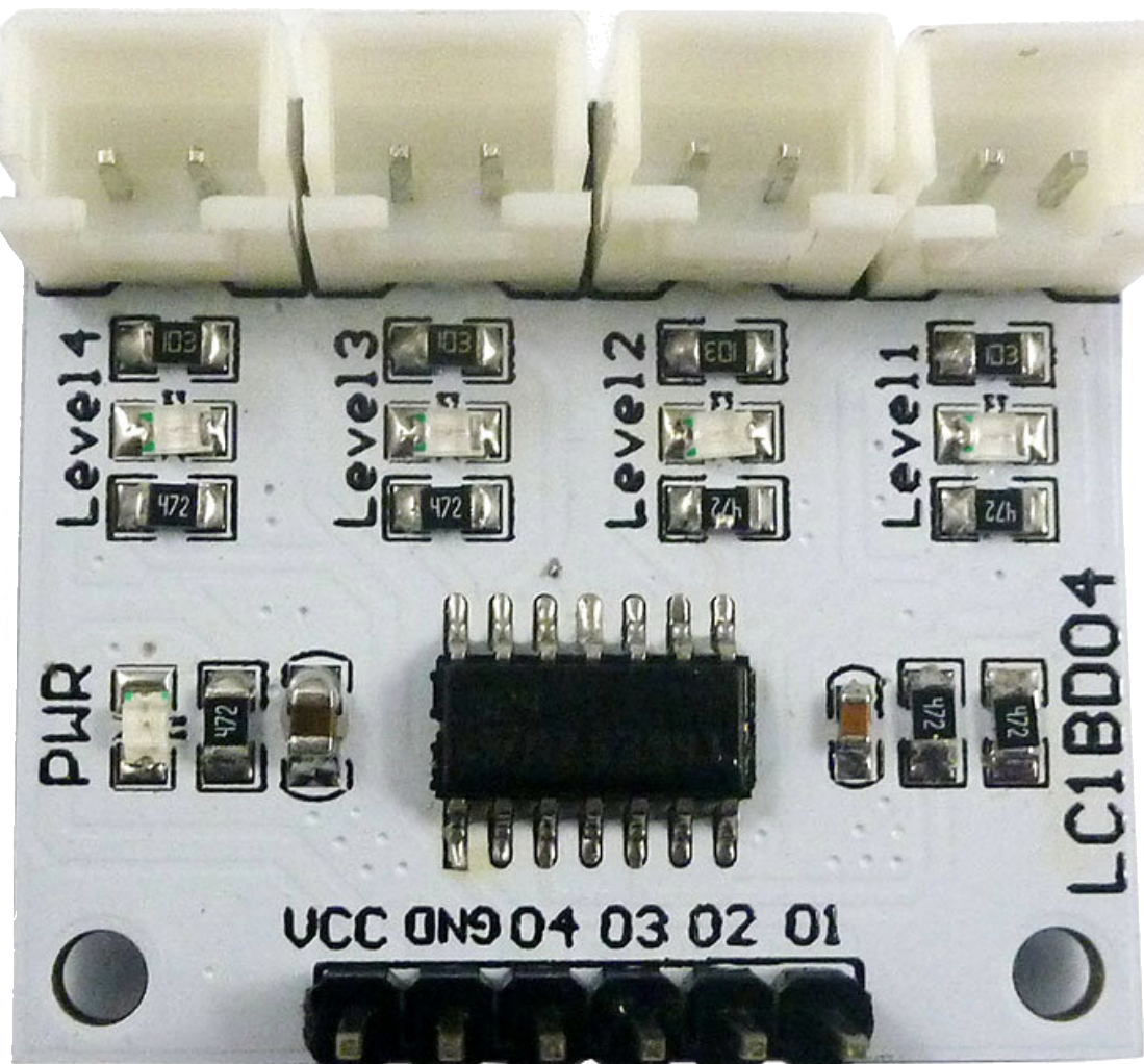
The LC1BD04 Water Level Monitor is a versatile device designed to detect and monitor water levels in tanks, reservoirs, or other liquid storage systems. It uses sensors to provide real-time data on water levels, enabling automated control of pumps, alarms, and other connected systems. This component is ideal for applications where precise water level management is critical, such as in irrigation systems, water treatment plants, and household water tanks.
Explore Projects Built with LC1BD04 Water Level Monitor
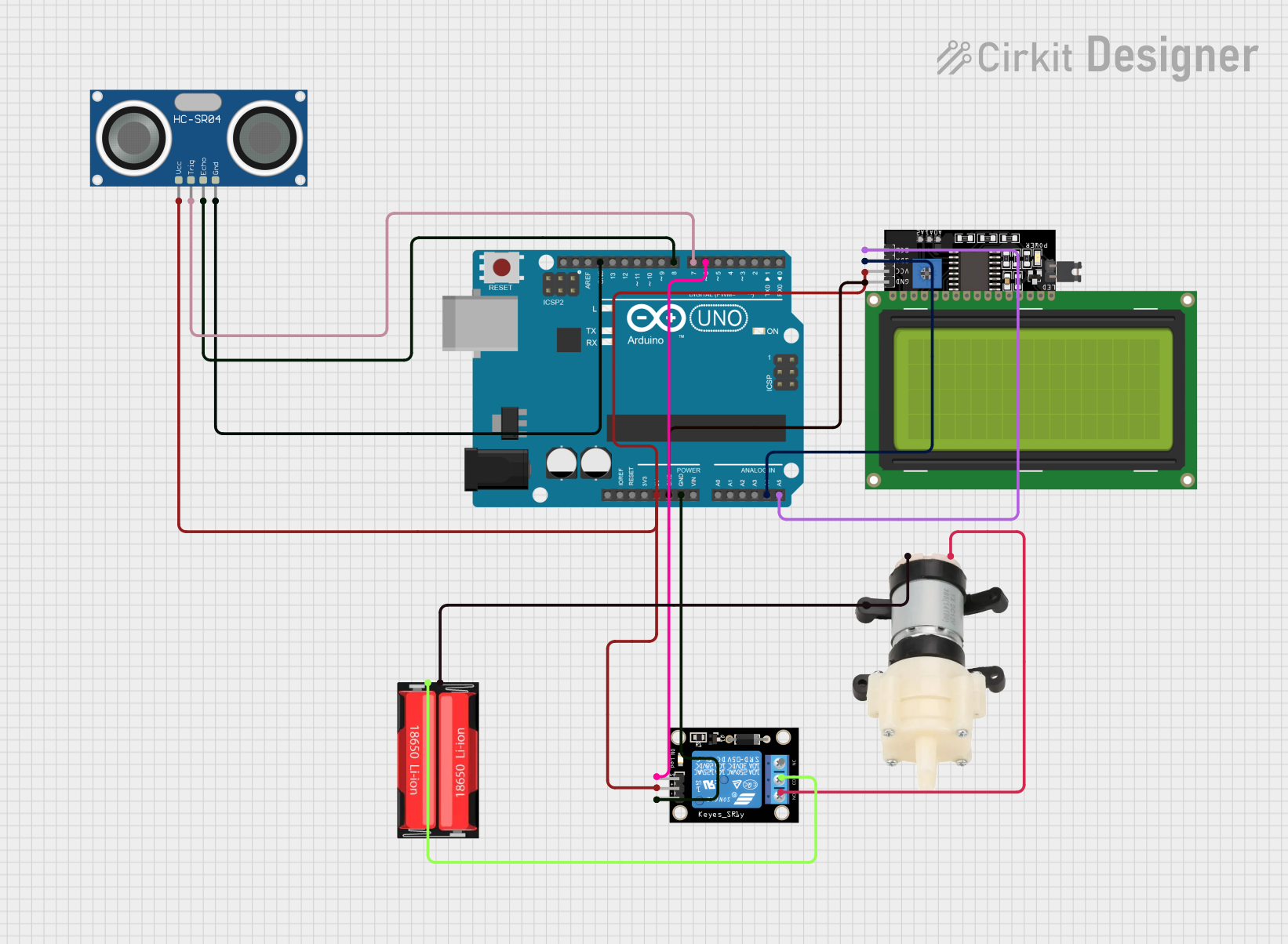
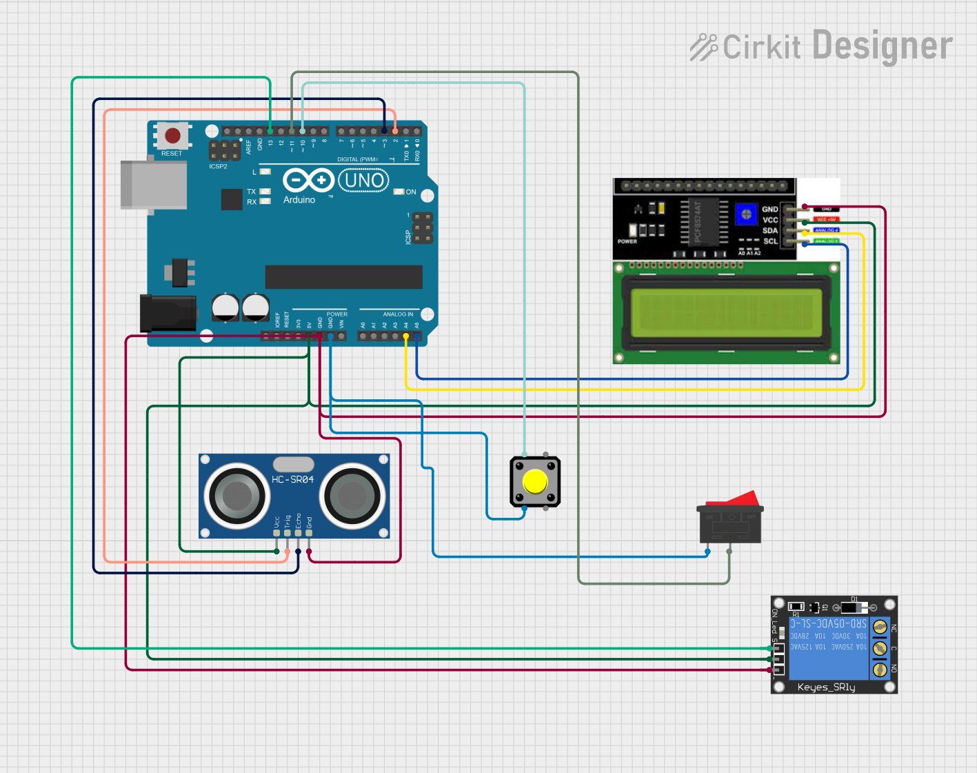

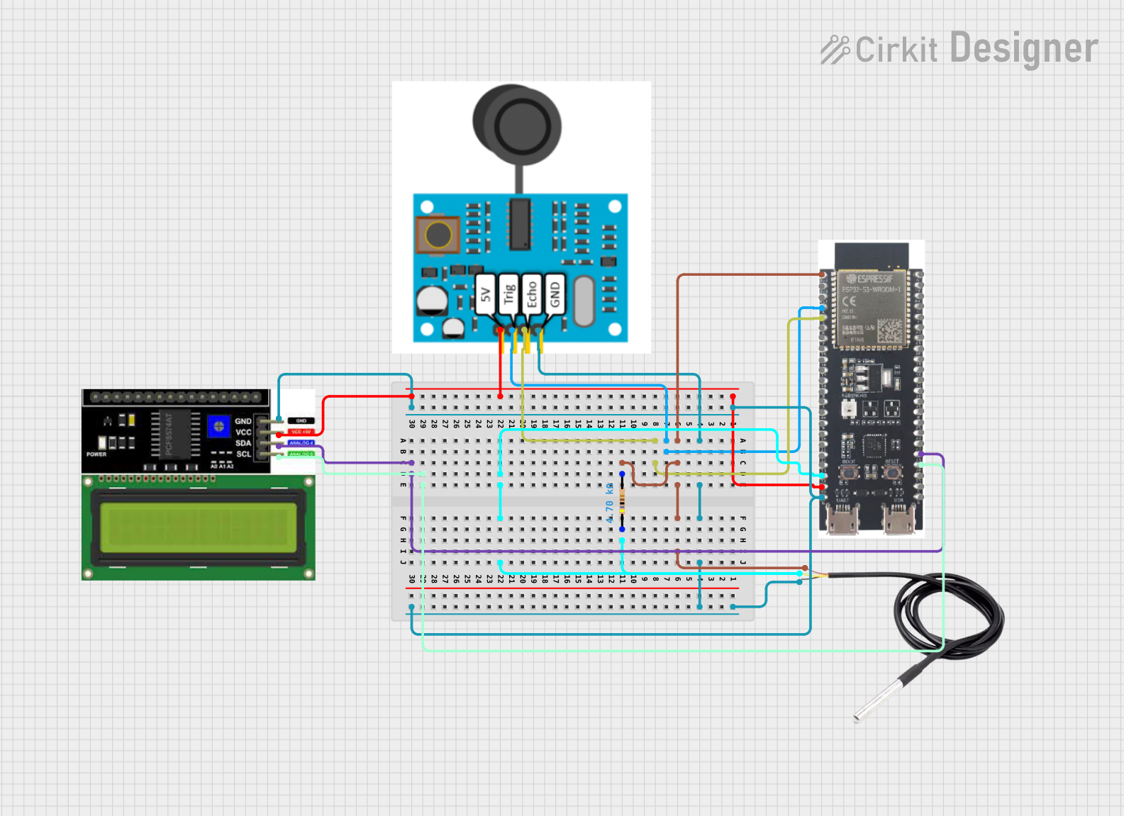
Explore Projects Built with LC1BD04 Water Level Monitor
Common Applications and Use Cases
- Automated water pump control to prevent overflow or dry running
- Water level monitoring in industrial tanks and reservoirs
- Integration with alarm systems for water level alerts
- Smart home water management systems
- Agricultural irrigation systems
Technical Specifications
The LC1BD04 Water Level Monitor is designed for reliable and efficient operation. Below are its key technical details:
General Specifications
| Parameter | Value |
|---|---|
| Operating Voltage | 5V DC |
| Operating Current | ≤ 20mA |
| Output Type | Digital (High/Low) |
| Sensor Type | Conductive water level probes |
| Detection Range | 0–100% of tank height |
| Operating Temperature | -10°C to 60°C |
| Dimensions | 50mm x 30mm x 15mm |
Pin Configuration and Descriptions
The LC1BD04 module typically has a 4-pin interface. Below is the pinout:
| Pin Name | Description |
|---|---|
| VCC | Power supply input (5V DC) |
| GND | Ground connection |
| OUT | Digital output signal (High when water detected) |
| NC | Not connected (reserved for future use) |
Usage Instructions
The LC1BD04 Water Level Monitor is simple to integrate into a circuit. Follow the steps below to use it effectively:
Connecting the LC1BD04
- Power Supply: Connect the
VCCpin to a 5V DC power source and theGNDpin to the ground. - Output Signal: Connect the
OUTpin to a microcontroller (e.g., Arduino UNO) or a relay module for controlling external devices like pumps or alarms. - Sensor Probes: Place the conductive probes at the desired water levels in the tank (e.g., low, medium, high). Ensure proper insulation to avoid short circuits.
Example Circuit with Arduino UNO
Below is an example of how to connect the LC1BD04 to an Arduino UNO for water level monitoring:
Circuit Diagram
VCC→ Arduino 5VGND→ Arduino GNDOUT→ Arduino digital pin (e.g., D2)
Sample Code
// LC1BD04 Water Level Monitor Example Code
// This code reads the water level signal and turns on an LED if water is detected.

const int waterSensorPin = 2; // Pin connected to LC1BD04 OUT
const int ledPin = 13;        // Built-in LED on Arduino

void setup() {
  pinMode(waterSensorPin, INPUT); // Set water sensor pin as input
  pinMode(ledPin, OUTPUT);        // Set LED pin as output
  Serial.begin(9600);             // Initialize serial communication
}

void loop() {
  int waterLevel = digitalRead(waterSensorPin); // Read water level signal

  if (waterLevel == HIGH) {
    // Water detected
    digitalWrite(ledPin, HIGH); // Turn on LED
    Serial.println("Water detected!");
  } else {
    // No water detected
    digitalWrite(ledPin, LOW);  // Turn off LED
    Serial.println("No water detected.");
  }

  delay(500); // Wait for 500ms before next reading
}
Important Considerations and Best Practices
- Probe Placement: Ensure the probes are securely placed at the desired water levels and are not in contact with each other.
- Power Supply: Use a stable 5V DC power source to avoid erratic behavior.
- Signal Noise: If the output signal is noisy, consider adding a pull-down resistor (10kΩ) to the
OUTpin. - Corrosion Prevention: Use corrosion-resistant materials for the probes to ensure long-term reliability.
Troubleshooting and FAQs
Common Issues and Solutions
| Issue | Possible Cause | Solution |
|---|---|---|
| No output signal | Incorrect wiring or loose connections | Verify all connections and wiring. |
| False water detection | Electrical noise or interference | Add a pull-down resistor to the OUT pin. |
| Corrosion on probes | Prolonged exposure to water | Use stainless steel or coated probes. |
| Output signal fluctuates | Unstable power supply | Use a regulated 5V DC power source. |
FAQs
Q1: Can the LC1BD04 detect non-conductive liquids?
A1: No, the LC1BD04 relies on conductive probes and is designed for use with conductive liquids like water.
Q2: Can I use the LC1BD04 with a 3.3V microcontroller?
A2: The LC1BD04 is designed for 5V operation. Use a level shifter or a 5V-tolerant input pin if connecting to a 3.3V microcontroller.
Q3: How many probes can I connect to the LC1BD04?
A3: The LC1BD04 supports multiple probes for different water levels, but the exact number depends on your circuit design.
By following this documentation, you can effectively integrate the LC1BD04 Water Level Monitor into your projects for reliable water level detection and control.